


R
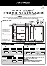
PANEL PREPARATION INSTRUCTIONS
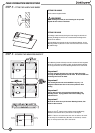
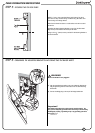
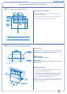
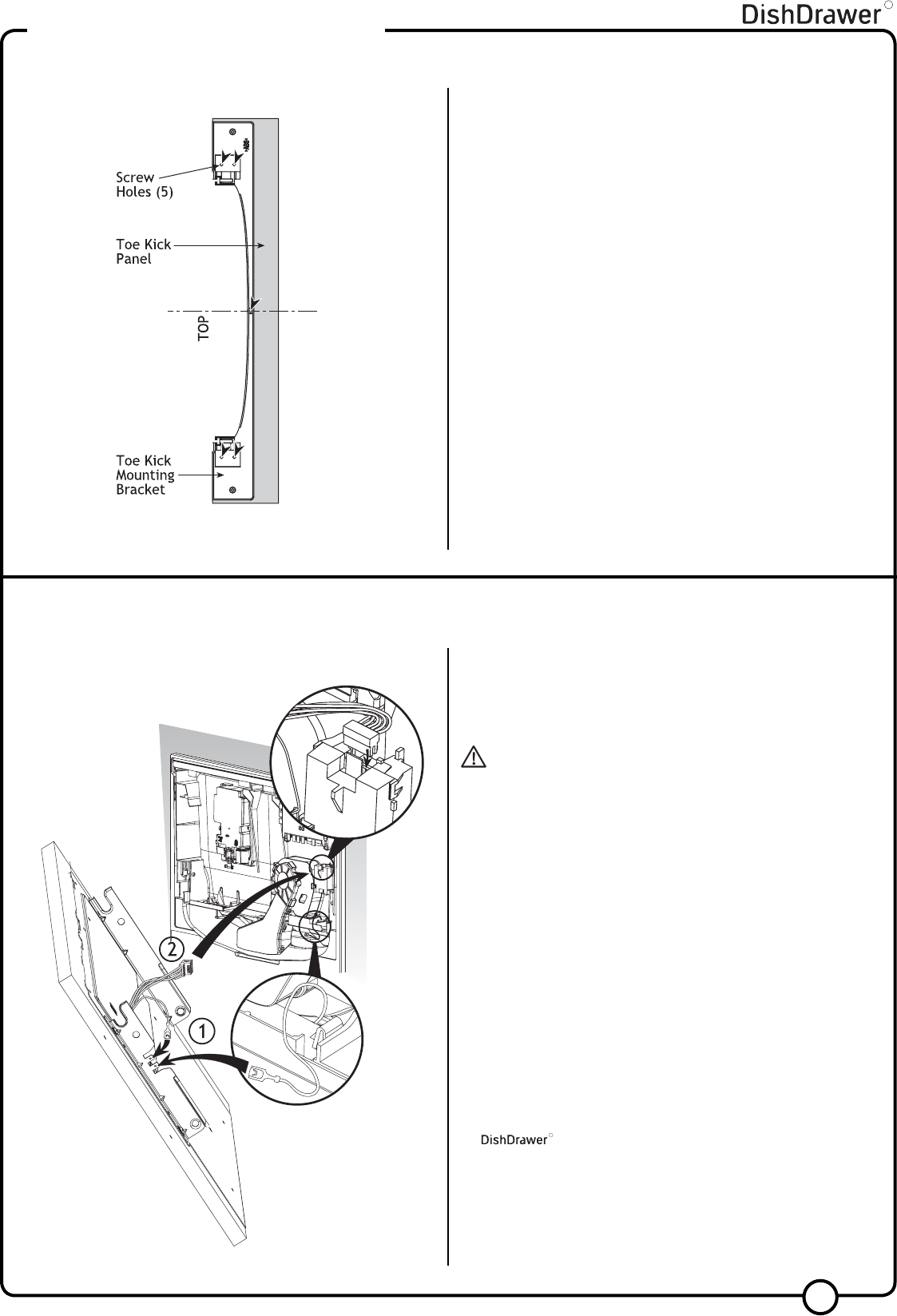
STEP 5: SECURING THE TOE KICK PANEL
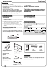
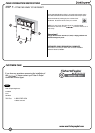
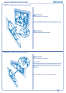
STEP 6: GROUNDING THE MOUNTING BRACKETS AND CONNECTING THE BADGE WIRES
WARNING!
Be sure the Product is not plugged in.
Important!
The Badge Isolator Board is an electrostatic sensitive device. Be
sure you are adequately grounded when connecting or disconnecting
the Badge by wearing a grounding strap or by grounding yourself to
the
R
.
5
NOTE: If using the supplied Black Prefinished Toe Kick,
proceed to Step 6 Grounding the Mounting Brackets and
Connecting the Badge Wires.
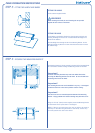
Place Toe Kick Panel face down on a soft surface and mark a vertical
center line.
Centralize the plastic Mounting Bracket on top of the Toe Kick Panel.
Align the top of the Bracket with the top of the Panel.
Using 5 of the
5
/
8
” (16mm) screws provided fix the Mounting Bracket to
the Toe Kick Panel.
1) Plug the green Badge grounding wire onto a Mounting Bracket tab.
Plug the grounding wire from the Product onto the other Mounting
Bracket tab.
2) Connect the Badge plug to the top of the Badge Isolator Box.