


FortiGate-5001FA2-LENC Security System Guide
16 01-30000-76602-20080606
Inserting a FortiGate-5001FA2-LENC board into a chassis Hardware installation
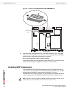
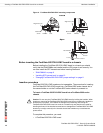
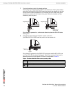
7 Turn both handles to their fully-closed positions.
The handles should hook into the sides of the chassis slot. Closing the handles
draws the FortiGate-5001FA2-LENC board into place in the chassis slot and into
contact with the chassis backplane. The FortiGate-5001FA2-LENC front panel
should be in contact with the chassis front panel. When the handles are fully-
closed they lock into place.
If the chassis is powered on, as the board slides into place the IPM LED starts
flashing blue.
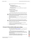
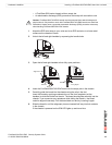
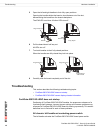
8 Fully tighten the left and right retention screws to lock the
FortiGate-5001FA2-LENC board into position in the chassis slot.
.
If the chassis is powered on the PWR LED turns green and the STA LED turns
red. The ACC LED also starts flashing red. After a few minutes, if the board is
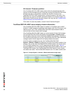
operating correctly the front panel LEDs are lit as described in Table 4.
Close
Fully Closed
and Locked
Alignment Pin
Alignment Pin
Handle
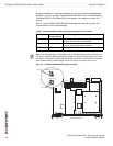
Table 4: FortiGate-5001FA2-LENC normal operating LEDs
LED State
PWR Green
ACC Off (Or flashing red when the system accesses the flash disk.)
STA Green
IPM Off
Tighten
Retention
Screw