


Chapter 2 Installation Instructions
15
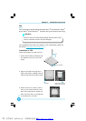
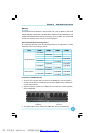
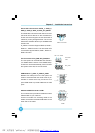
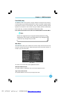
Front Panel Connector: FP1
This motherboard includes one connector for con-
necting the front panel switch and LED indicators.
HDD LED Connector (HDD-LED)
The connector connects to the case’s HDD indicator LED indicating the activity
status of hard disks.
Reset Switch (RESET)
Attach the connector to the Reset switch on the front panel of the case; the
system will restart when the switch is pressed.
Power LED Connector (PWRLED)
Attach the connector to the power LED on the front panel of the case. The Power
LED indicates the system’s status. When the system is in S0 status, the LED is
on. When the system is in S1, S3, S4, S5 status, the LED is off.
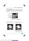
Power Switch Connector (PWRSW)
Attach the connector to the power button of the case. Pushing this switch allows
the system to be turned on and off rather than using the power supply button.
+ -
+ -
1
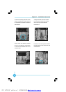
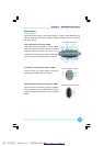
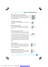
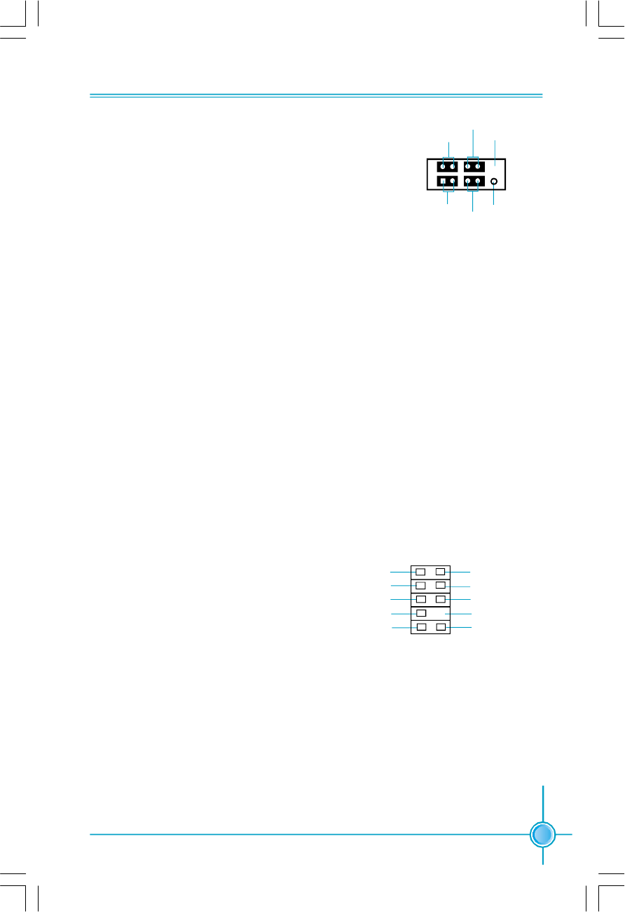
Audio Connector: F_AUDIO_1
The audio connector supports HD au-
dio standard. It provides two kinds of
audio output choices: the Front Audio,
the Rear Audio. Front Audio supports
re-tasking function.
FP1
NCHD-LED
RESET
PWRLED
PWRSW
Empty
SENSE_SEND
1
F_AUDIO_1
PORT2_L
PORT1_L
PORT1_R
PORT2_R
AUD_GND
PRESENCE_J
SENSE1_RETURN
SENSE2_RETURN
Empty
PDF 文件使用 "pdfFactory" 试用版本创建 www.fineprint.com.cn