


4 Identifying External Components
This chapter describes the front panel, rear panel, and LED indicators of the Switch.
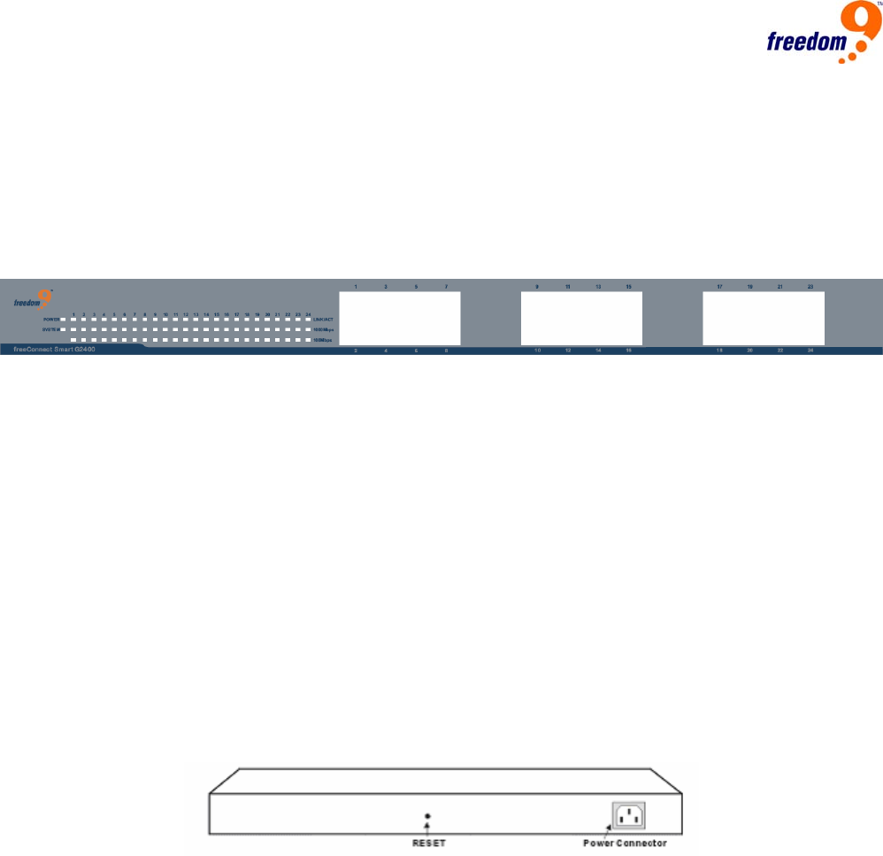
4.1 Front Panel
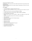
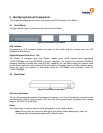
The figure below (Figure 4) shows the front panels of the Switch.
Figure 4: Front panel of the Switch
LED Indicator:
Comprehensive LED indicators display the status of the switch and the network (see the LED
Indicators section below).
Gigabit Ethernet Ports (Port 1~24):
The Switch is equipped with two Gigabit copper ports which support auto negotiating
10/100/1000Mbps and auto MDI/MDIX crossover detection. The support for automatic MDI/MDIX
crossover detection provides true “plug and play” capability, you just need to plug the network cable
into the Switch and don’t need to worry if the end node is a computer, switch, or other network device.
These two ports can operate in half-duplex mode for 10/100Mbps and full-duplex mode for
10/100/1000Mbps.
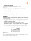
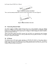
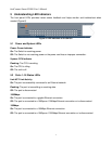
4.2 Rear Panel
Figure 5: Rear panel of the Switch
AC Power Connector:
This is a three-pronged connector that supports the power cord. Plug in the female connector of the
provided power cord into this connector, and the male into a power outlet. Supported input voltage
range is 100-240V AC at 50-60Hz.
Reset:
The Reset button is used to reset all of the settings back to the factory default.
Note: Be sure that you record the settings of your Switch before performing a reset, as
all settings will be erased after pressing the “Reset” button.