ADA-16FX-ETHERNET
Chapter 5 Connectors
UG-960011-11 - 10 - © Fujitsu Microelectronics Europe GmbH
5 Connectors
5.1 Ethernet connector (X1)
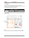
This is the Ethernet jack for connecting the ADA-16FX-ETHERNET to the Ethernet. The
connector complies with the 10BaseT standard. The used connector has integrated
transformers for transmit and receive lines.
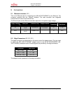
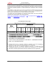
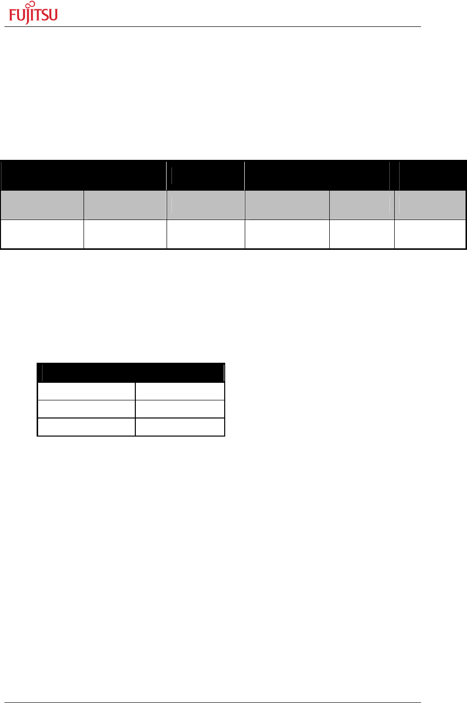
The Ethernet jack and the Ethernet controller depends on the power supply voltage:
Supply Voltage
Used jack Ethernet Chip Adapter Board
Rx
Transitions
Tx
Transitions
5V
Halo HFJ11-
1043E
CS8900CQZ
ADA-16FX-
ETHERNET
1:1 1:1.41
3V3
Halo HFJ11-
1041E
CS8900CQ3Z - 1:1 1:2.5
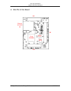
5.2 Edge Connectors (X2, X3, X11)
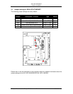
The edge connectors are assembled on the bottom side of the adapter board. They are used
to attach the ADA-16FX-ETHERNET adapter board to the SK-16FX-EUROSCOPE (SK-
16FX-100PMC) evaluation board. All used signals are provided by the edge connectors.
Connector MCU Pins
X2 (1 – 20) 1 – 20
X3 (71 – 100) 71 – 100
X11 (51 – 70) 51 – 70
The adapter board is powered via the edge connectors.


