


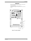


Installation Conditions
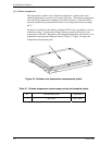
3.3.2 Signal segment and power supply segment
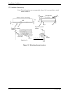
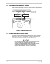
Figure 3.8 shows each segment of the SATA interface connector and pin numbers.
Power suppl
y
segment
P1 pins in the power
supply segment
View from the
connector side
View from the
PCA side
Si
g
nal se
g
ment
S1 pins in the si
g
nal
segment
Figure 3.8 Power supply pins (CN1)
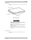
3.3.3 Connector specifications for host system
The connector of host system for mating with the disk drive must be compliant
with Serial-ATA Revision 2.5 specification. For detail of requirements about
SATA interface connector, refer to the "Serial-ATA Revision 2.6."
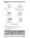
The connection reliability per number of insertion/extractions varies
with the condition of the connection with the host system.
Therefore, we recommend that the customer evaluate the connector
on the customer's system and select it from the connectors
complying with the Serial ATA Revision 2.6 specification.
3-10 C141-E280