


Pin assignment of internal ports
10 - English A26361-D1562-Z120-2-6319
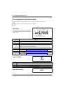
Pin assignment of internal ports
The pin assignment of some internal connections is shown in English in the following.
i
Some of the following connectors may be optional!
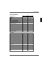
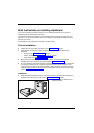
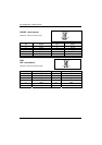
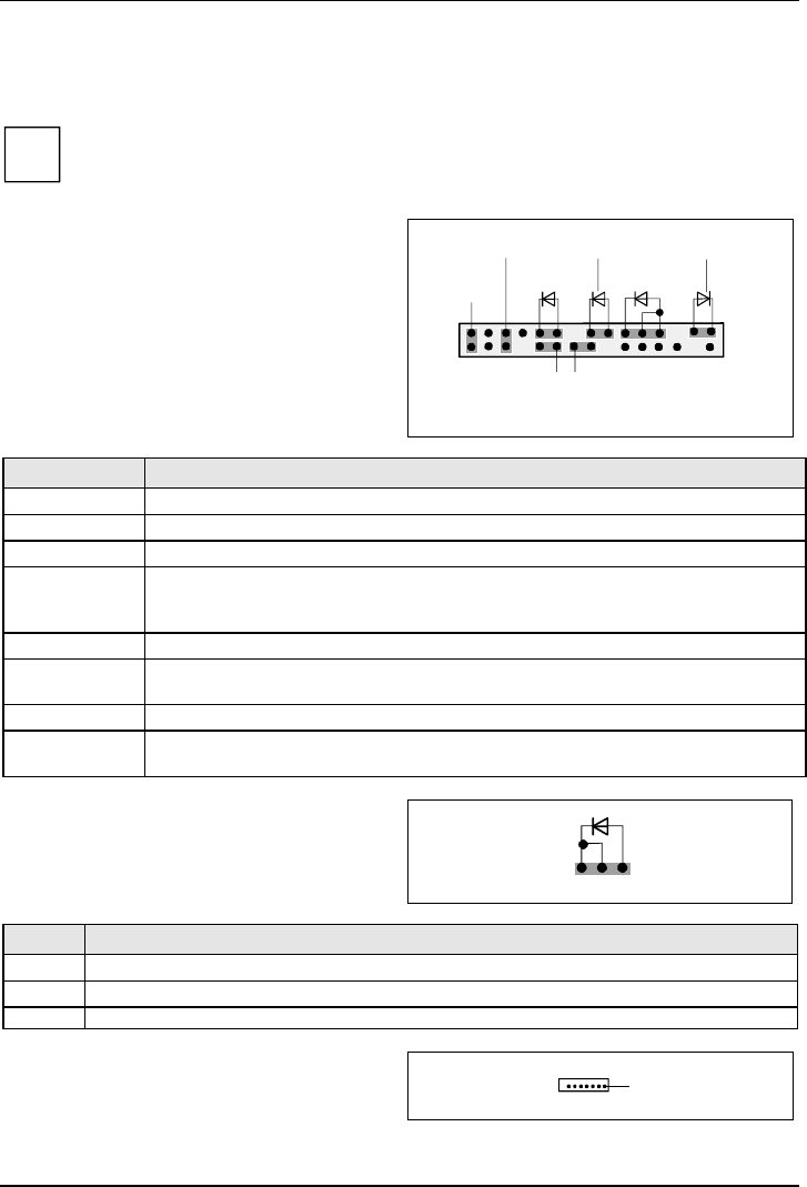
Front panel
Watch the poling of the LEDs. The positive pole
of the connection cables is often indicated with a
coloured wire.
1) The same interface
2) 2pin or 3pin connector possible
1
2
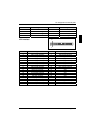
HD-LED
Power On/Off
SCSI LED Input
1)
Reset
Power On
LED
2)
Sleep LED
Message LED
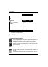
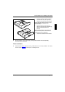
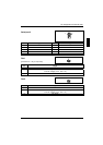
Connection Note
Reset
Power On/Off
HD LED
SCSI Activity
Input
Attention: Do not connect to the LED connections of an SCSI controller! This
connection is intended for a cable with a 4-pin connector. An SCSI controller
reports activity (low-active) via this cable.
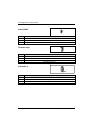
Message LED
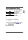
Power On LED Indicates the system state APM or ACPI together with the Sleep LED (see
chapter entitled "APM and ACPI system status, energy-saving modes").
Speaker 0,5 W at 8 Ohm
Sleep LED Indicates the system state APM or ACPI together with the Power-On LED (see
chapter entitled "APM and ACPI system status, energy-saving modes").
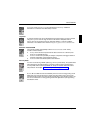
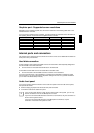
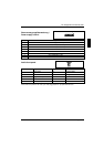
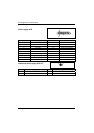
Power On LED II
1
3
Pin Signal
1 Power On LED (Anode)
2 Power On LED (Anode)
3 Power On LED (Cathode)
Serial ATA (internal)
1