TechNotes_D2963_V1.0 Copyright 2010 FUJITSU LIMITED
15
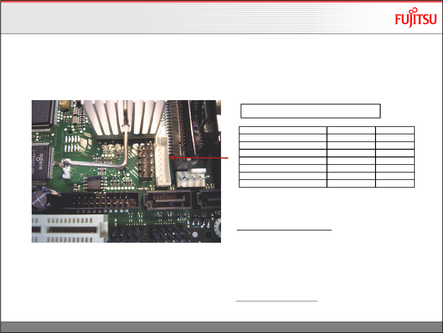
Ground GND 1
Ground GND 2
Backlight Brightness CTRL tbd 3
Power 5V VCC 4
Power 5V VCC 5
Backlight On/Off Control BL On/Off 6
Power 12V +12V 7
Power 12V +12V 8
1
8
Backlight Inverter Connector: JST PHR-8
Note:
BacklightBrightnessControl: Providesa variable DC voltage
between 0V and ~ 3.5V via an RC filter (2,2kOhm / 20uF).
Basically the voltage level can be selected via BIOS
Setup –Peripheral Configuration –Brightness Control.
If this control signal is used, the system integrator is
responsible for the implementation of a backlight converter
that fits to the control output voltage range.
Backlight On/Off Control: Active High, 3.3V
Note: Polarity can be changed via BIOS Setup
(Not supported by pilot production mainboardsGS5x!)
max. load: 2A per pin!
Display Options
Backlight Inverter Connector Details
Display Options
Backlight Inverter Connector Details


