


6
FTP-623MCL400/FTP-623DCL002
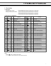
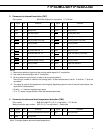
No. Signal I/O Contents No. Signal I/O Contents
1 PRSTB I Data strobe 2 PRSTB-RET —
Connected to logic GND
3 PRDT0 I Data 0 4 PRDT0-RET —
Connected to logic GND
5 PRDT1 I Data 1 6 PRDT1-RET —
Connected to logic GND
7 PRDT2 I Data 2 8 PRDT2-RET —
Connected to logic GND
9 PRDT3 I Data 3 10 PRDT3-RET —
Connected to logic GND
11 PRDT4 I Data 4 12 PRDT4-RET —
Connected to logic GND
13 PRDT5 I Data 5 14 PRDT5-RET —
Connected to logic GND
15 PRDT6 I Data 6 16 PRDT6-RET —
Connected to logic GND
17 PRDT7 I Data 7 18 PRDT7-RET —
Connected to logic GND
19 ACKNLG O Data input acknowledge 20 ACKNLG-RET —
Connected to logic GND
21 BUSY O Busy 22 BUSY-RET —
Connected to logic GND
23 RINF2 O Printer status 24 INPRM-RET —
Connected to logic GND
25 SLCTIN I Printer select 26 INPRM I Reset
27 RINF1 O Printer status 28 RINF3 O Printer status
29 ATF I Paper feed request 30 GND — Logic GND
Notes:
• Symbol “——” means a negative logic signal.
• “–RET” signal is a return signal of the twisted pair cable.
• “I” or “O” means a signal direction from the interface board side.
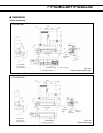
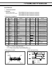
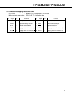
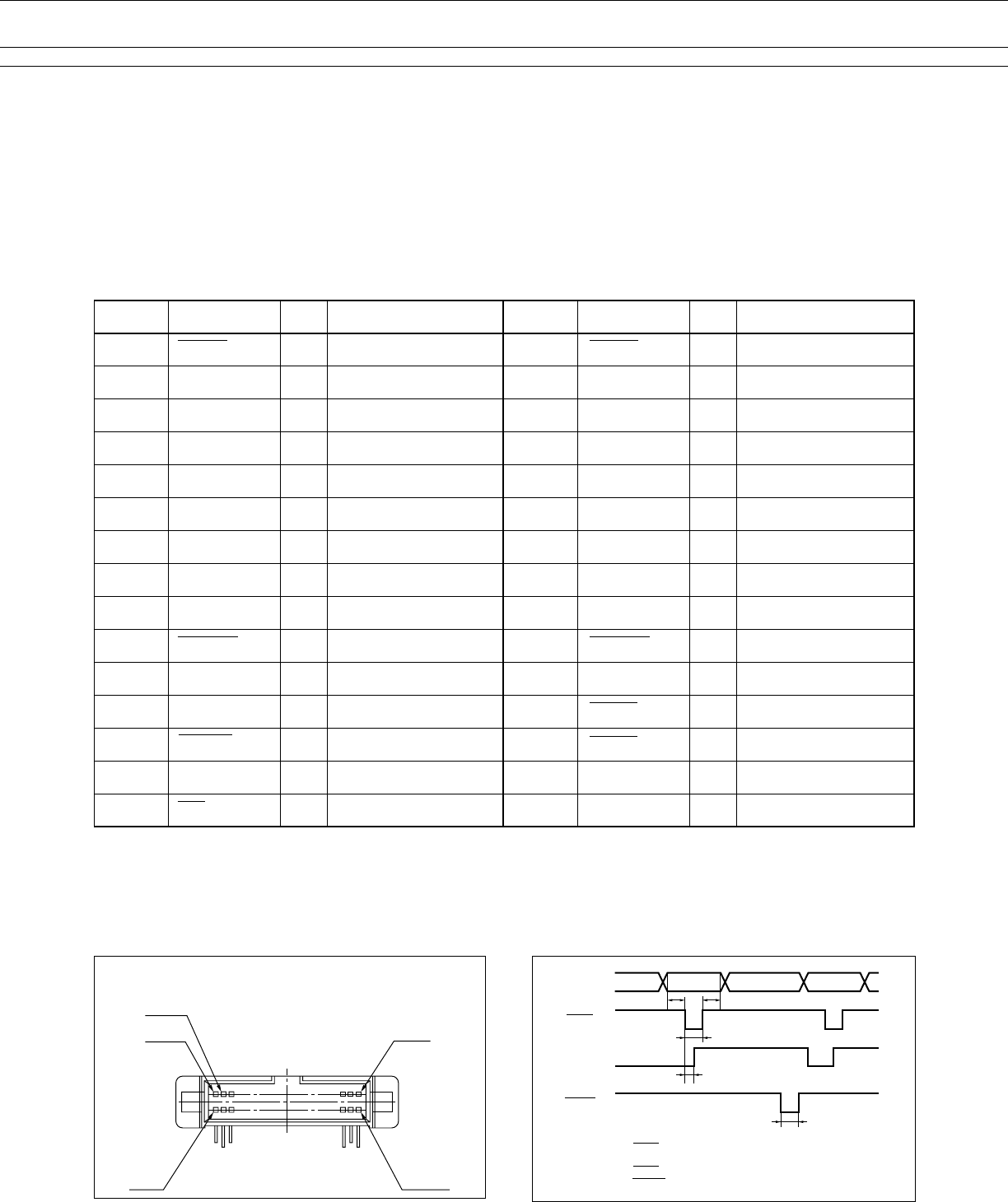
(3) Connector pin number
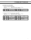
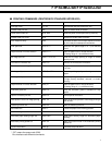
(4) Data input signal timing
FCN-215Q030-G/0 (Fujitsu Components) or
equivalent
(2) Connector pin assignment
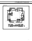
■ INTERFACE
1. Centronics standard
(1) Connector
Connector part number : FCN-215Q030-G/0 (Fujitsu Components) or equivalent
Mating connector part number : FCN-217Q030-G/0 (Fujitsu Components) or equivalent
FCN-214Q030-G/0 (Fujitsu Components) or equivalent
FCN-215Q030-G/0 (Fujitsu Components) or equivalent
291
3
230
PRDT0~7
PRSTB
BUSY
ACKNLG
t1 t3
t2
t4
t5
Data set time
PRSTB pulse width
Data hold time
PRSTB to BUSY= “H”
ACKNLG pulse time
:t1≥0.5 µsec
:t2≥0.5 µsec
:t3≥0.5 µsec
:t4≤0.5 µsec
:t5=1.0~1.5 µsec