


9
FTP-623MCL400/FTP-623DCL002
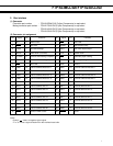
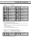
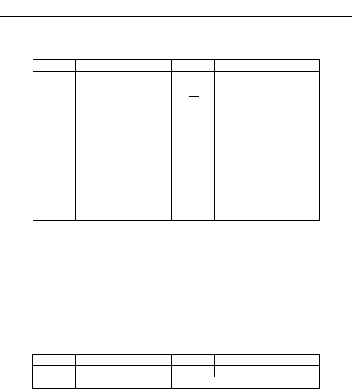
3. Connector for thermal head drive (CN7)
Part number : 52030-2610 (Molex) or equivalent → P.C.B side
No. Signal I/O Contents No. Signal I/O Contents
1 BAT — Power for head 2 BAT — Power for head
3 GND — Head ground 4 GND — Head ground
5 HD2 O Print data output 6 LAT O Printing data latch
7 HDV O Power for logic 8 HCLK O Printing transmitting clock
9 ENB8 *
1, 2
O Printing enable (not used) 10 ENB7 *
1,2
— Printing enable (not used)
11 ENB6 O Printing enable 12 ENB5 O Printing enable
13 VREF O Power for thermistor 14 TMP O Temperature detection
15 *
3
— Connected with No. 17 16 HDV O Power for logic
17 *
3
— Connected with No. 15 18 *
4
— Head rank specify (not used)
19 *
4
— Not used (pulled-up by resistor) 20 ENB4 O Printing enable
21 ENB3 O Automatic paper loading 22 ENB2 O Printing enable
23 ENB1 O Printing enable 24 GND — Paper-out detection
25 GND — Printing enable 26 BAT — Power for head
Notes:
*1: Mechanism selection signal and the printing enable signal for 3” mechanism.
*2: Not used at the combination with 2” mechanism.
*3: At the mechanism side, this pin number is for the printing data 2.
Since this pin number is used for the printing data 1 at the interface board, the No. 15 and No. 17 pins are
connected.
*4: This signal is used for the adjustment of printing duty depending upon the rank of thermal head resistor. Not
used at this interface board.
• Symbol “——” means a negative logic signal.
• “I” or “O” means a signal direction from the interface board side.
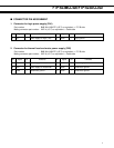
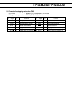
4. Connector for abnormal head temperature detection (CN6)
Part number : B3B-XH-A-WHITE (J.S.T) or equivalent → P.C.B side
Mating connector part number : XHP-3 (J.S.T) or equivalent → Cable side
No. Signal I/O Contents No. Signal I/O Contents
1 TMPER O
Abnormal head temperature detection
2 N.C. — Not connected
3 GND — Logic ground
Note: This signal detects abnormal head temperature.