


5
5. Connecting to the User System
■ Connecting
Mount the supplied NQPACK on the user system before using the MB2146-261.
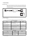
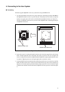
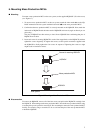
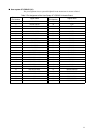
1. To connect the header board to the user system, match pin 1 indicated by the index mark (▲) on
the NQPACK mounted on the user system with pin 1 indicated by the index mark (an angle cut
linearly at one place only in silk screen) on the header board and then insert it (see “Figure 4”) .
The pins of YQPACK are thin and easy to bend. Insert NQPACK after confirming that the pins
of YQPACK are not bent.
Figure 4 Index Position
2. Insert each screw for securing the header board into each of the four tapped holes on the header
board, and then tighten the screws diagonally. The center screw hole is not used. To tighten the
screws, use the special screwdriver supplied with the NQPACK to equally tighten the four screws
in sequence. Tightening the screws too tight might result in a defective contact.
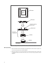
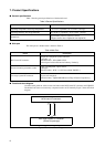
3. Connect the MCU board to the header board while being careful not to excessively force the NQ-
PACK. The MCU board can be connected to the header board only in the correct orientation as
they have an incorrect insertion prevention header socket to prevent a reverse connection. Figure
5 illustrates how the MCU board, header board, NQPACK, and user system are connected togeth-
er.
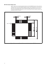
14
13
1
52
40
39
27
26
NQPACK index mark
Header board index mark