C141-F037-02EN 5 - 1
CHAPTER 5 PRINCIPLE OF OPERATION
5.1 Outline
5.2 Disk Drive Configuration
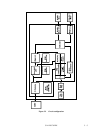
5.3 Circuit Configuration
5.4 Power-On Sequence
5.5 Factory-Calibration
5.6 Read/Write Circuit
5.7 Servo Control
This chapter explains the general design concepts of the disk drive. It also explains the main parts,
sequences, servo control method, and the main electrical circuits of the drive at the block level.
5.1 Outline
The principle of operation of this disk drive can be divided into two parts. The first part explains
the mechanical parts of the drive (see Section 5.2). The second part explains the servo data
recorded on a magnetic disk and explains drive control (see Sections 5.3 to 5.7).
5.2 Disk Drive Configuration
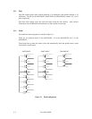
The main disk drive subassemblies are a disk enclosure (DE) and printed-circuit boards (also
called printed circuit assemblies (PCA)).
The DE contains all the moving parts of the disk drive. That is, DE contains disks, heads,
spindle mechanism, and actuator, and also air filters.
These parts are explained in Subsections 5.2.1 to 5.2.5.
Each PCA contains the electric circuit of the disk drive. See Section 5.3 for explanations of
these electric circuits.


