C141-F037-02EN 5 - 3
5.2.3 Spindle mechanism
The spindle mechanism consists of a disk stack assembly and a spindle motor. The disk stack
assembly is directly driven by the direct drive type DC spindle motor. The rotational frequency
of this spindle motor is 10,025 rpm. A counterelectromotive force is generated by the drive
current in the spindle motor coil. A fixed rotational frequency of the spindle is maintained by
comparing the frequency of the counterelectromotive voltage with the reference frequency
generated by the crystal oscillator.
5.2.4 Actuator
The actuator consists of a voice coil motor (VCM) and a head carriage. The voice coil motor
moves the head carriage to the inner or outer side of the disk. The head carriage position is
controlled by feeding back servo information read by the heads.
5.2.5 Air filters
There are two filters in the disk drive, the breathing filter and the circulation filter. The
breathing filter is used to conduct filtered air into and out of the DE. Starting or stopping the disk
generates heat in the spindle motor in the DE, causing temperature variation in the DE. This
temperature variation expands or compresses the air in the DE causing the filtered air to come in
or go out of the DE. At times when the atmospheric air pressure changes, such as when the disk
drive is shipped by airmail, filtered air enters the DE.
The circulation filter catches dust or dirt that may get inside the DE. Air is continuously
circulating inside the drive and passing through the circulation filter, utilizing a closed loop air
circulation system that uses the blower effect of the rotating disks.
5.3 Circuit Configuration
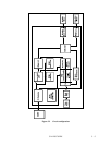
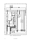
Figure 5.2 shows the circuit configuration of IDD.
(1) Read/write circuit
The read/write circuit uses LSI devices and a head IC to improve data reliability and prevent
external noise from causing errors.
The read/write circuit also contains a VFO circuit and an 16/17 RLL code modem circuit.
The read/write circuit also contains a synthesizer for the constant density recording method.
(2) Servo circuit
Voice coil motor position/speed control is carried out by a closed loop servo system and carries
out feedback control based on servo information recorded on the data surface. Analog servo data
is converted into a digital signal, and is then processed by a DSP. The digital signal is then
converted into an analog signal which then controls the voice coil motor.


