C141-F037-02EN 5 - 7
5.5 Factory-Calibration
Factory calibration is intended to correct errors in the mechanisms and circuits and maintain
stable seek, read or write operation.
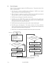
(1) External force adjustment
Even if the actuator stops at a fixed position, disturbing forces such as an FPC force and air
movement caused by disk rotation are exerted. Also, when an instruction that reduces the voice
coil motor current to 0 is issued, a very small offset current flows in the control circuit. Such
disturbing forces are collectively handled, as external forces, by the control circuit. The external
forces depend on the disk type and actuator position. Self-calibration measures and records
external forces on the 256 representative cylinders, from the outermost to innermost cylinder. To
compensate for the effect of the external forces, the offset values that were measured in each
actuator position are applied to the circuit. This provides stable seek operation.
(2) Servo gain adjustment
The servo control circuit gives stable operation when the gain of the servo loop is constant.
However, servo loop gains vary slightly, depending on each device and cylinder position (outer,
center, and inner cylinders) according to the characteristics of the magnet used in the VCM. To
compensate, the servo gain is measured at representative positions, from the outermost to
innermost, for each device. Measurement is similar to the external force adjustment. Measured
values are stored, as a table, in flash memory. To adjust servo gain, the DSP refers to this table,
and creates a control table for constant loop gain. The DSP stores this table in flash memory.
(3) Head position correction
When a write head is independent of the corresponding read head and both heads are driven by
the rotary actuator, the heads have different center positions depending on the cylinder position.
To compensate, the read head must be centered when writing. To adjust precisely, the offset
value for each head of each drive must be measured and stored in flash memory. At correction,
the DSP calculates the offset value for the head and cylinder position, and centers the read head
when writing.
5.6 Read/Write Circuit
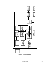
The write/read circuit consists of a head IC unit (in DE), write circuit, read circuit, and a write
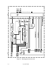
frequency adjust circuit. Figure 5.4 is a block diagram of the read/write circuit.
5.6.1 Head IC
The head IC is mounted inside the DE. The head IC has a preamplifier and a write current
driver, and has a write error detection function. Each channel is connected to each data head,
and is switched with a serial port. If a write error, such as a head short-circuit or head
disconnection is detected, an error signal (WUS) is generated.


