Command Specifications
3 -
108
C141-E167
The “Transfer byte count” field in the CDB specifies the total number of bytes of the header and
buffer data which can be received by the INIT. The IDD reads the data from the data buffer from
the top (Address X ‘000000’), then adds the 4-byte header to it and transfers it to the INIT. Data
transfer is completed at the point when the number of bytes of the header and data from the IDD’s
data buffer, specified in the “Transfer byte length” field, has been transferred, or at the point when
transfer of the header and all the data in the IDD’s data buffer, to the final byte position, has been
completed. When zero is specified in the “Transfer byte length” field, this command is terminated
without executing a data transfer.
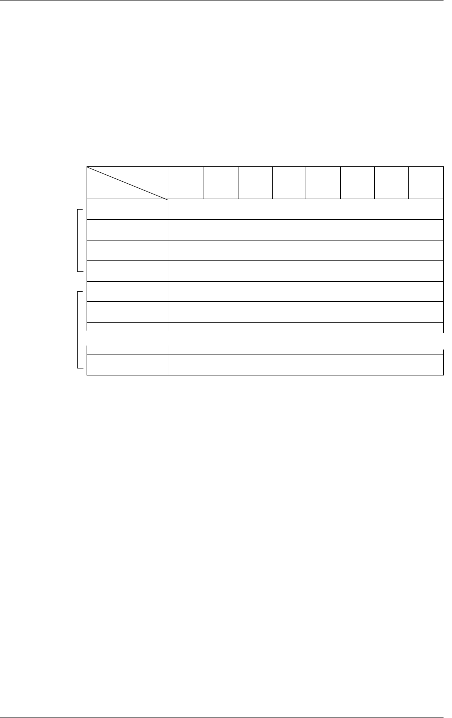
The format of the data transferred to the INIT when this mode is specified is shown in Figure 3.25.
Bit
Byte
76543210
0 00000000
1 Effective Buffer Data Length (MSB)
2 Effective Buffer Data Length
3 Effective Buffer Data Length (LSB)
4 Buffer Data (Byte 0)
5 Buffer Data (Byte 1)
n Buffer Data (Byte n–4)
Figure 3.25 READ BUFFER command: buffer data (Mode = 0000, 0001)
The “Effective buffer data length” field in the header indicates the size of the data buffer (byte
length). This value indicates the size of the IDD’s data buffer that can be used by the WRITE
BUFFER and READ BUFFER commands without relation to the length specified in the “Transfer
byte length” field in the CDB or the length of the data actually stored in the data buffer by the
WRITE BUFFER command. When this mode is specified, the “Effective buffer data length” shows
the size (cache segment volume) of the IDD’s entire data buffer area. Also, the length of the buffer
data transferred to the INIT by this command is the value for the number of bytes in the [“Transfer
byte length” field in the CDB – 4 bytes] or the value indicated in the “Effective buffer data length”
field in the header, whichever is smaller.
(2) Mode = 0, 0, 0, 1: Header + data, with address specification
The format of the data transferred to the INIT when this mode is specified is the same as the format
of the data in the case of Mode = 0, 0, 0, 0, with the data stored in the IDD’s data buffer transferred
to the INIT following the 4-byte header. In this mode, the address in the data buffer can be specified
in the “Buffer offset” field in the CDB.
~
~
~
~
~
~
Header
Data


