


Installation Requirements
4-4 C141-E198
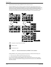
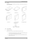
c) Tightening torque of screw must be secured with 0.59N· m (6kgf· cm) ±12%.
d) Impact caused by the electric driver must be within the device specifications.
e) Must be handled on an anti-static mat.
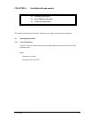
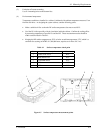
5.0 or less
5.0 or less
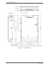
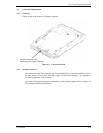
Figure 4.3 Mounting frame structure
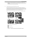
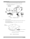
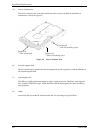
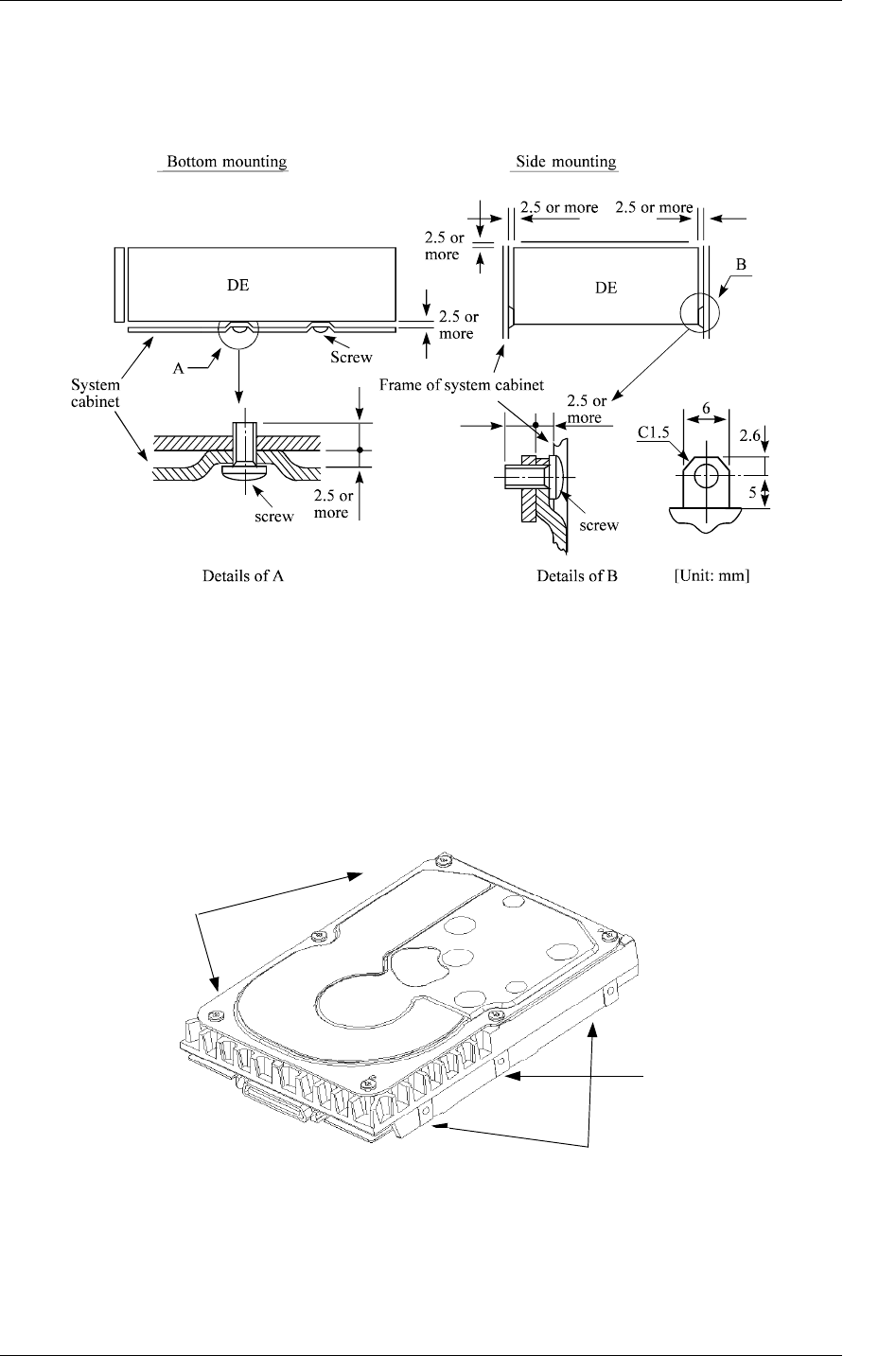
(2) Limitation of side-mounting
Mount the IDD using the 4 screw holes at the both ends on the both sides as shown in Figure 4.4. Do
not use the center hole by itself.
In case of using the center hole, it must be used in combination with 2 holes on both ends.
(Total 6 screws for 6 holes enclosed)
Use four holes (No.1-4) to mount.
Holes for
mounting screw.
Do not use center holes.
Holes for mounting screw
1
2
3
4
Figure 4.4 Limitation of side-mounting