


4.3 Connection Requirements
C141-E198 4-9
4.3 Connection Requirements
4.3.1 Connector
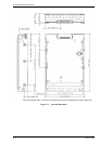
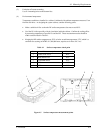
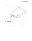
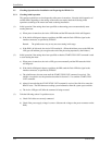
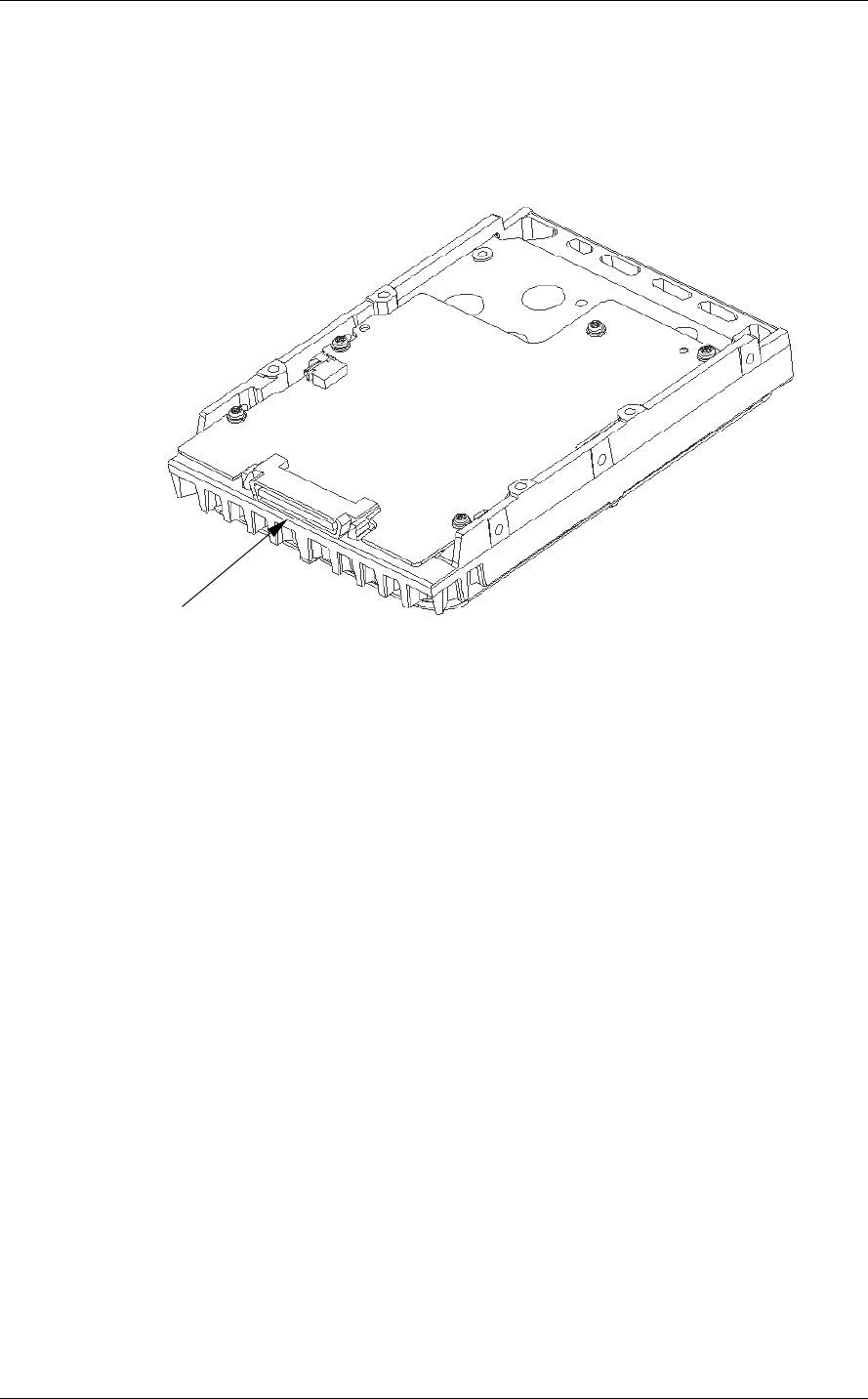
Figure 4.9 shows the locations of interface connector.
Interface connector (CN1)
(including power supply connector)
Figure 4.9 Connector location
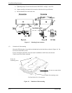
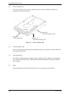
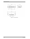
4.3.2 Interface connector
The connector for the Fibre Channel Loop is an unshielded SCA-2 connector which has two 20-
pin rows spaced 1.27 mm (0.05 inch) apart. Figure 4.10 shows the connector. See Appendix A
for signal assignments on the connector.
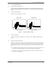
For details on the physical/electrical requirements of the interface signals, refer to Chapter 1 in
Fibre Channel Interface Specifications.