


4.2 Power Supply Requirements
C141-E198 4-7
4.2 Power Supply Requirements
(1) Allowable input voltage and current
The power supply input voltage measured at the power supply connector pin of the IDD (receiving
end) must satisfy the requirement given in Subsection 2.1.3. (For other requirements, see Items (4)
below.)
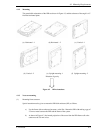
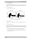
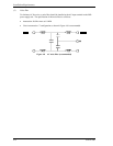
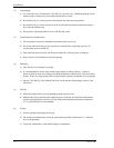
(2) Current waveform (reference)
Figure 4.7 shows the waveform of +12 VDC.
Current (500mA/div)
MAS3735FC
Current (500mA/div)
Time (2 sec/div)
MAS3367FC
Current
(
500mA/div
)
Time (2 sec/div)
Figure 4.7 Current waveform (+12 VDC)
(3) Power on/off sequence
The order of the power on/off sequence of +5 VDC and +12 VDC, supplied to the IDD, does not
matter.
(4) Sequential starting of spindle motors
After power is turned on to the IDD, a large amount of current flows in the +12 VDC line when the
spindle motor rotation starts. Therefore, if more than one IDD is used, the spindle motors should be
started sequentially using one of the following procedures to prevent overload of the power supply
unit.
a) Issue START/STOP commands at more than 12-second intervals to start the spindle motors. For
details of this command specification, refer to Fibre Channel Interface Specifications.
b) Turn on the +12 VDC power in the power supply unit at more than 12-second intervals to start
the spindle motors sequentially.