5.5 Checking Operation after Installation and Preparing the IDD for Use
C141-E198 5-7
c) Continuous sending of the Fault LED Out signal to the interface connector indicates the initial
self-diagnosis has detected a problem. In this event and if the situation allows, sense data should
be obtained by issuing the REQEUST SENSE command from the initiator (host system). Sense
data is information required for troubleshooting.
The Active LED goes off while the IDD command is being executed.
For some commands, however, since the Active LED goes off for only a
fraction of a second, the Active LED looks like it flashes or remains lit.
5.5.2 Checking connection
When the initial operation is checked normally after power is turned on, check that the IDD is
connected to the loop from the host system. Although checking the connection depends on the
structure of the host system, this section describes the general procedures.
(1) Checking procedure
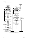
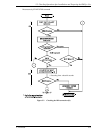
Issuing the commands and determining the end status depends on the start mode of the spindle motor
and UNIT ATTENTION report mode (specified with setting terminal). Figure 5.1 shows the
recommended checking procedure for the mode that the motor starts when power is turned on.
Figure 5.2 shows for the mode that the motor starts by the START/STOP command. In these
recommended checking procedures, following items are checked.
Note:
Following steps a) to e) correspond to a) to e) in Figures 5.1 and 5.2.
a) Issue the TEST UNIT READY command and check that the IDD is connected correctly to
the loop and the initial operation after power is turned on ended normally. The command
issue period of the TEST UNIT READY command shall be more than 20 ms.
b) To control starting of the spindle motor from the host system, issue the START/STOP
UNIT command to start the spindle motor.
c) Check the loop operations with the WRITE BUFFER and READ BUFFER commands.
d) Start the IDD self-diagnostic test with the SEND DIAGNOSTIC command and check the
basic operations of the controller and disk drive.


