


C141-E205 4-5
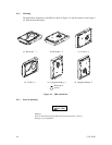
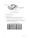
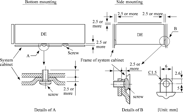
(1) Mounting frame structure
Special attention must be given to mount the IDD disk enclosure (DE) as follows.
a) Use the frame with an embossed structure, or the like. Mount the IDD with making a gap
of 2.5 mm or more between the IDD and the frame of the system.
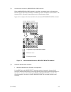
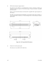
b) As shown in Figure 4.4, the inward projection of the screw from the IDD frame wall at the
corner must be 5.0 mm or less.
c) Tightening torque of screw must be secured with 0.59N·m (6kgf·cm) ±12%.
d) Impact caused by the electric screwdriver must be within the device specifications.
e) Must be handled on an anti-static mat.
Figure 4.4 Mounting frame structure
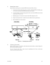
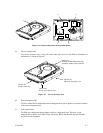
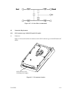
(2) Limitation of side-mounting
Mount the IDD using the 4 screw holes at the both ends on the both sides as shown in Figure 4.5.
Do not use the center hole by itself.
In case of using the center hole, it must be used in combination with 2 holes on both ends.
(Total 6 screws for 6 holes enclosed)
5.0 or less
5.0 or less