


13
MB3842/MB3845
■
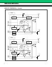
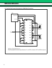
FUNCTIONAL DESCRIPTION
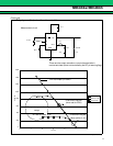
Current Limit Setting
By placing resistance between the CS and GND pins, the current limit can be set between 100mA and 600mA
within ±30% accuracy (V
IN
= 5 V, current limit at 600mA). Because the setting value is dependent on V
IN
voltage,
the user should select the optimum resistance value for the value of V
IN
voltage
. When the switching current
exceeds the set value, the OC pin goes to “L” level as an external notification signal, but there is no latching
function. To hold operation on “off” state, the input signal to the EN and EN
pins should be used.
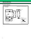
When a direct connection to GND is used, there is no current limitation.
When the connection is open, the switch is in a state of continuously held current limits.
Thermal Shutdown
The MB3842/MB3845 has a thermal shutdown function which turns the switch off and sets the latch to protect
the device when junction temperature exceeds 125°C.
At the same time the OC output signal goes to “L” level to notify external systems.
The latch function can be reset by sending a low signal to the EN input of the MB3842, or a high signal to the
EN
input of the MB3845.
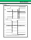
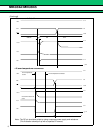
Slow Start
The on/off switching time can be delayed by applying capacitance between the SS and GND pins. Controlling
the on time can soften surge current to the load side capacitance when power is turned on.
For details, see “Css vs. t
ON
(SS) characteristics” on p. 9.
UVLO
A V
IN
voltage monitoring function is provided, so that when V
IN
voltage exceeds 2.3 V (typ) the OC pin voltage
goes to “H” level. When V
IN
voltage falls below 2.1V (typ), the OC output goes to “L” state.
Error Flag OC Pin
The OC pin produces a “L” signal in case of a UVLO, overcurrent, or over-temperature condition. In case of
overcurrent, the output has a pulse waveform. See P12.
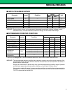
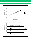
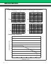
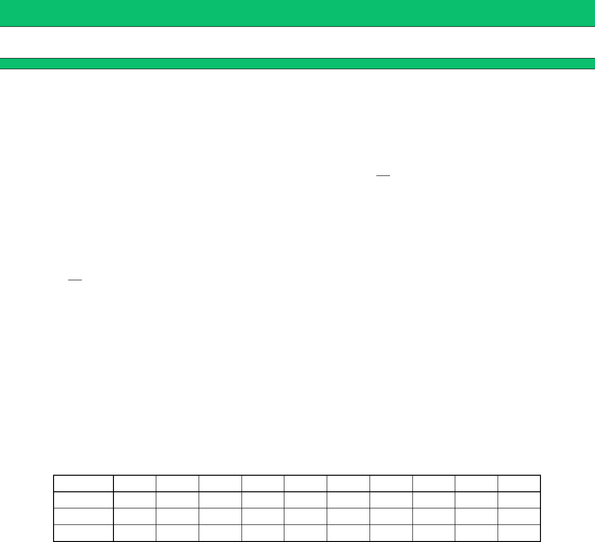
(note) Output current limit setting resistance values are shown on P9, and in the following table. (CS pin-to-GND)
Standard Values
V
IN
/I
SW
0.1 A 0.2 A 0.3 A 0.4 A 0.5 A 0.6 A 0.7 A 0.8 A 0.9 A 1.0 A
V
IN
5.0V 6.2 kΩ 4.3 kΩ 3.3 kΩ 2.7 kΩ 2.2 kΩ 2.0 kΩ 1.8 kΩ 1.6 kΩ 1.4 kΩ 1.3 kΩ
V
IN
3.3V 9.1 kΩ 5.6 kΩ 4.3 kΩ 3.3 kΩ 2.7 kΩ 2.4 kΩ 2.0 kΩ 1.8 kΩ 1.6 kΩ 1.5 kΩ
V
IN
2.5V 13 kΩ 7.5 kΩ 5.1 kΩ 3.9 kΩ 3.0 kΩ 2.7 kΩ 2.2 kΩ 2.0 kΩ 1.8 kΩ 1.6 kΩ