


3
MB3842/MB3845
■
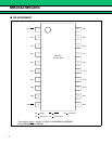
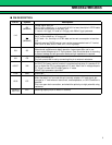
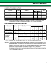
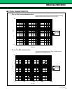
PIN DESCRIPTION
Pin no. Symbol Descriptions
1/10
EN
(MB3842)
Control signal input pin.
Set “H” to turn switch on, “L” to turn toff. At 0.8 V or less, the chip is in STBY state
and current consumption is less than 1µA.
“L” level is 1.4V (typ), “H” level is 1.6V (typ), with 200mV (typ) hysteresis.
EN
(MB3845)
Control signal input pin.
Set “L” to turn switch on, “H” to turn off.
At “H” level = V
IN
, the chip is in STBY state and current consumption is less than
1µA.
Normally used as CMOS inverter input, so that recommended use is “L” level at
GND +0.5V or less, and “H” level is V
IN
-0.5V or greater.
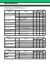
2/9 SS
Slow start setting pin. Used to adjust the switch on/off timing.
Add external capacitance to delay operation. Leave open when not in use.
In open mode voltages up to 12 V are present. Care should be taken in mounting
to prevent leakage current generation because high impedance is required.
3/8 CS
Current limit setting pin.
The limit current level is set by connecting this pin to external resistance.
4/5/6/7 VIN
Switch output pin.
An UVLO (V
IN
power monitor function) is provided so that when V
IN
reaches 2.3V
(typ.) or higher the OC pin voltage goes to “H” level. Also if the V
IN
voltage drops to
2.1 V (typ.) or lower the OC output goes to “L” state.
200mV (typ) hysteresis is provided.
11/20 GND Ground pin.
12/19 OC
External notification pin.
When the switch is in on mode this pin normally outputs a “H” level signal, but
changes to “L” level when an overcurrent, overtemperature, or UVLO condition is
detected.
This is an open drain connection, and should be pulled up to high potential using
resistance.
13/14/15
16/17/18
OUT Switching output pin.(N-ch MOSFET source)