xviii C156-E142-02EN
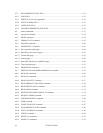
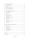
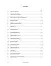
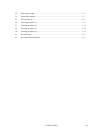
TABLES
page
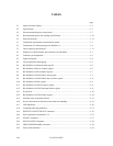
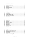
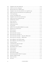
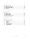
2.1 Model and order number.......................................................................................................2 - 1
2.2 Specifications........................................................................................................................ 2 - 3
2.3 Environmental and power requirements................................................................................ 2 - 7
2.4 Recommended optical disk cartridge specifications..............................................................2 - 10
2.5 Disk specifications ................................................................................................................2 - 13
3.1 Temperature requirements at measurement points ................................................................3 - 3
3.2 Temperature at each measuring point (Reference)................................................................3 - 4
3.3 Cable connector specifications..............................................................................................3 - 13
4.1 Differences in Host Interface Specifications of Each Model. ............................................... 4 - 1
4.2 Connector pin assignments....................................................................................................4 - 2
4.3 Signal description..................................................................................................................4 - 4
4.4 I/O port functions and mapping.............................................................................................4 - 5
4.5 Bit definitions of Alternate Status register ............................................................................ 4 - 6
4.6 Bit definitions of Device Control register ............................................................................. 4 - 6
4.7 Bit definitions of Drive Address register...............................................................................4 - 7
4.8 Bit definitions of ATAPI Byte Count register....................................................................... 4 - 7
4.9 Bit definitions of ATAPI Block Device Select register ........................................................ 4 - 8
4.10 Bit definitions of Error register .............................................................................................4 - 8
4.11 Bit definitions of ATAPI Features register ........................................................................... 4 - 9
4.12 Bit definitions of ATAPI Interrupt Reason register .............................................................. 4 - 9
4.13 IO and Cod............................................................................................................................4 - 10
4.14 Bit definitions of ATAPI Status register ...............................................................................4 - 10
4.15 Alternate sector assignment criteria ...................................................................................... 4 - 13
4.16 ID error and read error detection criteria and error handling ................................................4 - 14
4.17 LED indications .................................................................................................................... 4 - 20
4.18 Command codes and parameters...........................................................................................4 - 21
4.19 IDENTIFY PACKET DEVICE command............................................................................4 - 22
4.20 Device parameter information (1/5) ......................................................................................4 - 23
4.21 PACKET command ..............................................................................................................4 - 27
4.22 DEVICE RESET command .................................................................................................. 4 - 28
4.23 CHECK POWER MODE command.....................................................................................4 - 28
4.24 Power mode indication.......................................................................................................... 4 - 29


