C156-E142-02EN 3 - 21
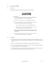
3) Connect the AT interface cable.
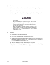
4) After each cable connector is connected, secure the cable so that the cable does not touch the
drive or the parts on the PCA or obstruct the flow of cooling air in the system cabinet.
3.9 Operation Confirmation and Preparation for Use after Installation
3.9.1 Confirming initial operations
This section provides the operation check procedures after the power is turned on.
(1) Initial operation when the power is turned on
# When the power is turned on, the drive starts initial self-diagnosis. The LED on the front
panel is on for 1 second during initial self-diagnosis.
# If an error is detected during initial self-diagnosis, the LED on the front panel blinks.
# In case of not inserted the cartridge, when the power is turned on, the eject motor
automatically turns once.
(2) Checks if errors occur at initial self-diagnosis
# Make sure that the cables are connected correctly.
# Make sure that the supply voltage is correct. (Measure the voltage at the power supply
connector of the optical drive.)
# Make sure that the settings of all terminals are correct.
# If the LED on the front panel blinks continuously, an error was detected during initial self-
diagnosis. In this case, issue the REQUEST SENSE command from the initiator (host system)
to obtain sense data for error analysis.
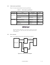
The BUSY LED is on while the optical disk drive is executing seek,
write, or read operations. The BUSY LED is on momentarily, so it
seems as if it blinked or is off.
The eject motor turns once when the power is turned on so that in case
the spindle motor position deviates due to shocks received by the drive
during transport the position is corrected to allow the cartridge to be
inserted normally. If the cartridge fails to be inserted, remove the
cartridge and turn on the drive power to turn the eject motor once and
reinsert the cartridge.


