


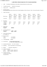
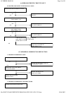
5-5 TRANSISTOR & DIODE CIRCUIT
LOCATION
CIRCUIT FUNCTION DESCRIPTION
D901 ~ D904
Bridge Rectifier for AC Source
D909
Half-Wave Rectifier for Start CKT
D910
Clamp Diode for Snubber CKT
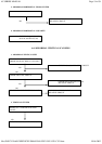
D919
Rectifier for Output Voltage
D922
Rectifier for Output Voltage
D923
Rectifier for Output Voltage
D925
Rectifier for Output Voltage
D927
Forward Bias when Q403 Turn-off to Protect B+ Block CKT
D929
B+ Feed Back Rectifier from F.B.T Pulse
Q904
Start CKT Amplifier Transistor
Q907, Q908
Use for Off-Mode to Cut-off 6.3V Supply Voltage
Q909, Q910
Use for Standy-By or Suspend Mode to Cut-off 14.5V Supply Voltage
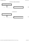
Q912, Q920
Push-Pull Topology to Drive Q911
Q401
Turn-on at Power ON/OFF and Change Mode to Protect Hor.Block
Q402
HOR. Driver Transistor
Q407, Q408
As a Switcher for H-Size Correction CKT
Q410, Q426
H-Size Corection Mosfet (Q426 15" only)
Q404, Q405
As Differential Amp. to Drive Q406
Q406
Darlington Transistor for H-Size Control
Q703
As a Switcher to Mute Screen when Abnormal Qccurring
Q704, Q705
Unit Brightness Control CKT
Q601, Q707
Develop Blanking Signal
Q813, Q814
A Amplifier to Corection and Support Clamp Signal
Page
11
of
59
4V SERIES MANUAL
05.06.2002
file://D:\PC%20AOC\SERVICE%20MANUAL\FSC\154V\154V
-
C551.htm