


4. ADJUSTMENT
4-1 ADJUSTMENT CONDITIONS AND PRECAUTIONS
1. Approximately 30 minutes should be allowed for warm up before proceeding.
2. Adjustments should be undertaken only on those necessary elements since most of them have been carefully preset at the factory.
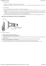
4-2 MAIN ADJUSTMENTS
4-3 ADJUSTMENT METHOD
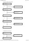
1. 15V, B + & HV protection voltage adjustment:
A. Chroma-2000 Signal generator or PC equivalent, set mode 1( VGA 640×480) pattern 1.0 .
B. Connect a DC voltage meter between TP 901 and ground, then adjust VR901 to be 15VDC.
C. Connect a DC voltage meter between TP 902 and ground, then adjust VR902 to be 88 VDC.
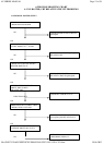
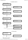
2. Factory preset timings adjustment:
A. When you turn on the monitor, the function LEDS will light up simultaneously for a while, then extinguish.
B. You can press the up/func two keys simultaneously, the most left four LEDS will light up for a while then extinguish.
C. Then you can select one of the eight functions including Contrast, Brightness, H-SIZE, H-CENTER, V-SIZE, V-
CENTER,
Pincushion and Trapezoid Simply press the function key and the LED will be light up corresponding to the one selected, then press
the up/down keys to get the factory presetting parameter value to your satisfaction.
D.
Then you will press the up/function two keys simultaneously again, the most right four LEDS will light up for a while then
extinguish, the factory preset timings adjustment is finished.
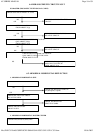
3. White balance and luminance adjustment:
A. Bias (low light) adjustment:
(a) Set mode 5 ( 800
×
600 Fh: 46.8KHz ) full white pattern.
(b) Adjust VR801, 802, 803, 804, 805, to make VR in the center position.
(c) Warm up more than 20 minute.
(d) Brightness set to max. Contrast set to min. full white pattern, then adjust FBT screen VR to make Y= 1.0FL
±
0.2FL
(e) Brightness set to raster just cutoff, contrast set to 4FL, then adjust CRT board VR805 (B-Bias) VR803 (R-
Bias) to make Y= 4
±
0.2 FL, x= 281
±
10, y= 311
±
10
B. Gain (High light) adjustment:
(a) Set mode 5 ( 800
×
600 Fh: 46.8KHz ) full white pattern.
(b) Brightness set to raster just cutoff and set the cantrast to max.
(c) Adjust VR801, 802 to make color code x=281
±
10, y=311
±
10.
C. Recheck item A&B to make sure both of them in spec.
D. Full white luminance:
(a) Set mode 5 ( 800
×
600 Fh: 46.8K ) full white pattern.
(b) Image size : H:260
±
4mm, V:195
±
4mm.
(c) Brightness set to raster just cut off and set the contrast to max.
(d)
Adjust VR701 to make sure white luminance at 28 FL.
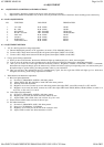
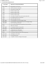
NO.
FUNCTION
LOCATION
DESIGNATION
1.
15V ADJ
PCB
-
MAIN
VR901
2.
B + ADJ
PCB
-
MAIN
VR902
3.
R.B. DRIVE
CRT
-
BOARD
VR801,802
4.
R.G.B. CUT
-
OFF
CRT
-
BOARD
VR803,804,805
5.
ABL ADJ
PCB
-
MAIN
VR701
6.
UP KEY
PCB
-
MAIN
SW101
7.
DOWN KEY
PCB
-
MAIN
SW102
8.
FUNCTION KEY
PCB
-
MAIN
SW103
Page
8
of
59
4V SERIES MANUAL
05.06.2002
file://D:\PC%20AOC\SERVICE%20MANUAL\FSC\154V\154V
-
C551.htm