


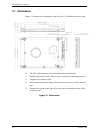
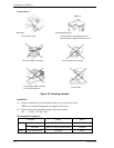
Installation Conditions
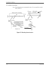
3.3.2 Signal segment and power supply segment
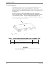
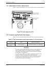
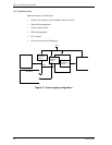
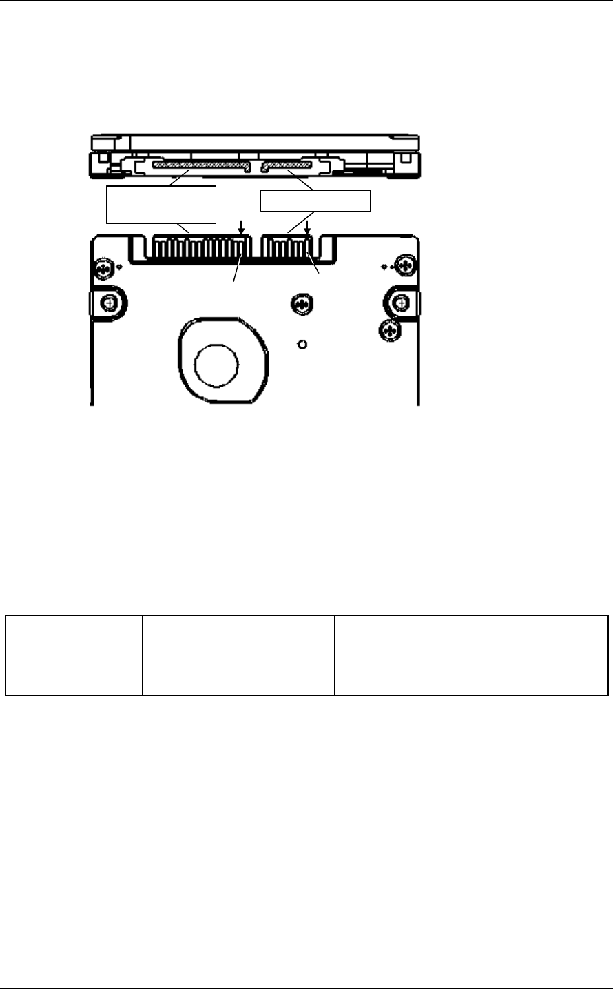
Figure 3.8 shows each segment of the SATA interface connector and pin numbers.
Power supply
segment
P1 pins in the power
supply segment
S1 pins in the signal
segment
View from the
connector side
View from the
PCA side
Signal segment
Figure 3.8 Power supply pins (CN1)
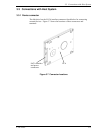
3.3.3 Connector specifications for host system
Table 3.2 lists the recommended specifications for the host interface connectors.
Table 3.2 The recommended connector specifications for the host system
Segment Name Model (Manufacturer)
SATA interface and
power supply
Host receptacle 67492-0220 (Molex) or compatibles
IMPORTANT
The above connector specifications for the host system indicate only
that its mating with the SATA interface connecter is confirmed.
Accordingly, the number connecter insertion/extractions including
hot plugging is not guaranteed.
The connection reliability per number of insertion/extractions varies
with the condition of the connection with the host system.
Therefore, we recommend that the customer evaluate the connecter
on the customer's system and select it from the several choices
including its equivalents (compatibles).
3-10 C141-E249