


Contents
Tables
Table 1.1 Specifications ........................................................................................ 1-4
Table 1.2 Examples of model names and product numbers .................................. 1-5
Table 1.3 Current and power dissipation ............................................................... 1-8
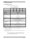
Table 1.4 Environmental specifications................................................................. 1-9
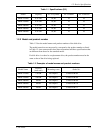
Table 1.5 Acoustic noise specification ................................................................ 1-10
Table 1.6 Shock and vibration specification........................................................ 1-10
Table 1.7 Advanced Power Management ............................................................ 1-14
Table 1.8 Interface power management............................................................... 1-16
Table 3.1 Surface temperature measurement points and standard values.............. 3-6
Table 3.2 The recommended connector specifications for the host
system.................................................................................................. 3-10
Table 5.1 Physical Layer Electrical Requirements ................................................ 5-7
Table 5.2 Connector pinouts................................................................................ 5-10
Table 5.3 Requirements for P11 as an output pin................................................ 5-11
Table 5.4 Shadow Block Register........................................................................ 5-16
Table 5.5 BIST combinations .............................................................................. 5-20
Table 5.6 Command code and parameters...........................................................5-29
Table 5.7 Diagnostic code ................................................................................... 5-43
Table 5.8 Operation of DOWNLOAD MICROCODE........................................ 5-45
Table 5.9 Example of rewriting procedure of data 512K Bytes
(80000h Bytes) of microcode............................................................. 5-46
Table 5.10 Features Field values (subcommands) and functions ........................ 5-56
Table 5.11 Format of device attribute value data ................................................ 5-60
Table 5.12 Format of guarantee failure threshold value data .............................. 5-60
Table 5.13 Off-line data collection status............................................................5-63
Table 5.14 Self-test execution status ................................................................... 5-63
Table 5.15 Off-line data collection capability ..................................................... 5-64
Table 5.16 Failure prediction capability flag....................................................... 5-64
Table 5.17 Drive error logging capability ........................................................... 5-64
Table 5.18 Log Directory Data Format................................................................ 5-65
Table 5.19 Data format of SMART Summary Error Log.................................... 5-66
Table 5.20 Data format of SMART Comprehensive Error Log .......................... 5-68
Table 5.21 SMART self-test log data format....................................................... 5-69
Table 5.22 Selective self-test log data structure .................................................. 5-70
Table 5.23 Selective self-test feature flags .......................................................... 5-71
Table 5.24 SCT command and the function ........................................................ 5-72
Table 5.25 Format of SCT STATUS Response................................................... 5-74
Table 5.26 SCT STATUS code ........................................................................... 5-76
C141-E249 xvii