


C141-E045-02EN5 - 80
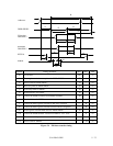
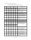
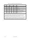
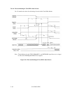
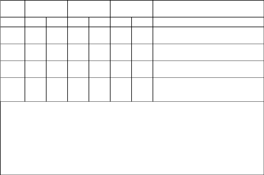
Table 5.12 Ultra DMA data burst timing requirements (2 of 2)
NAM
E
MODE 0
(in ns)
MODE 1
(in ns)
MODE 2
(in ns)
COMMENT
MIN MAX MIN MAX MIN MAX
t
IORDYZ
20 20 20 Pull-up time before allowing IORDY to
be released
t
ZIORDY
0 0 0 Minimum time device shall wait before
driving IORDY
t
ACK
20 20 20 Setup and hold times for DMACK-
(before assertion or negation)
t
SS
50 50 50 Time from STROBE edge to negation of
DMARQ or assertion of STOP (when
sender terminates a burst)
Notes:
1) t
UI
, t
MLI
and t
LI
indicate sender -to-recipient or recipient-to-sender interlocks, that is, one agent (either
sender or recipient) is waiting for the other agent to respond with a signal before proceeding. t
UI
is
an unlimited interlock, that has no maximum time value. t
MLI
is a limited time-out that has a
defined minimum. t
LI
is a limited time-out, that has a defined maximum.
2) All timing parameters are measured at the connector of the device to which the parameter applies.
For example, the sender shall stop generating STROBE edges t
RFS
after the negation of DMARDY-.
Both STROBE and DMARDY- timing measurements are taken at the connector of the sender.
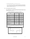
3) All timing measurement switching points (low to high and high to low) are to be taken at 1.5 V.