


C141-E056-01EN 5 - 31
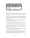
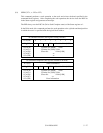
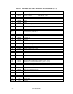
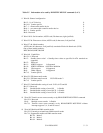
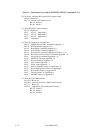
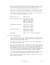
Table 5.5 Information to be read by IDENTIFY DEVICE command (2 of 3)
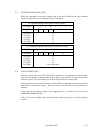
*1 Word 0: General configuration
Bit 15: 0 = ATA device 0
Bit 14-8: Vendor specific 0
Bit 7: 1 = Removable media device 0
Bit 6: 1 = not removable controller and/or device 1
Bit 5-1: Vendor specific 0
Bit 0: Reserved 0
*2 Word 10-19: Serial number; ASCII code (20 characters, right-justified)
*3 Word 23-26: Firmware revision; ASCII code (8 characters, Left-justified)
*4 Word 27-46: Model number;
ASCII code (40 characters, Left-justified), remainder filled with blank code (X'20')
One of three model numbers;
MPC3045AH, MPC3065AH
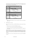
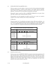
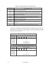
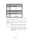
*5 Word 49: Capabilities
Bit 15-14: Reserved
Bit 13: Standby timer value 1 = Standby timer values as specified in ATA standard are
supported
Bit 12: Reserved
Bit 11: IORDY support 1=Supported
Bit 10: IORDY inhibition 0=Disable inhibition
Bit 9: LBA support 1=Supported
Bit 8: DMA support 1=Supported
Bit 7-0: Vendor specific
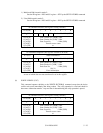
*6 Word 51: PIO data transfer mode
Bit 15-8: PIO data transfer mode X'02'=PIO mode 2
Bit 7-0: Vendor specific
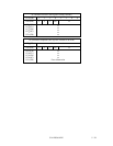
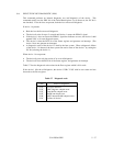
*7 Word 53: Enable/disable setting of word 54-58 ,64-70 and 88
Bit 15-3: Reserved
Bit 2: Enable/disable setting of word 88 1=Enable
Bit 1: Enable/disable setting of word 64-70 1=Enable
Bit 0: Enable/disable setting of word 54-58 1=Enable
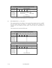
*8 Word 59: Transfer sector count currently set by READ/WRITE MULTIPLE command
Bit 15-9: Reserved
Bit 8: Multiple sector transfer 1=Enable
Bit 7-0: Transfer sector count currently set by READ/WRITE MULTIPLE without
interrupt supports 2, 4, 8 and 16 sectors.
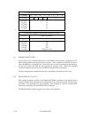
*9 Word 63: Multiword DMA transfer mode
Bit 15-8: Currently used multiword DMA transfer mode
Bit 7-0: Supportable multiword DMA transfer mode
Bit 2=1 Mode 2
Bit 1=1 Mode 1
Bit 0=1 Mode 0