


C141-E069-02EN3 - 10
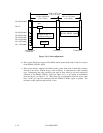
open
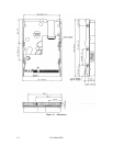
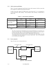
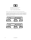
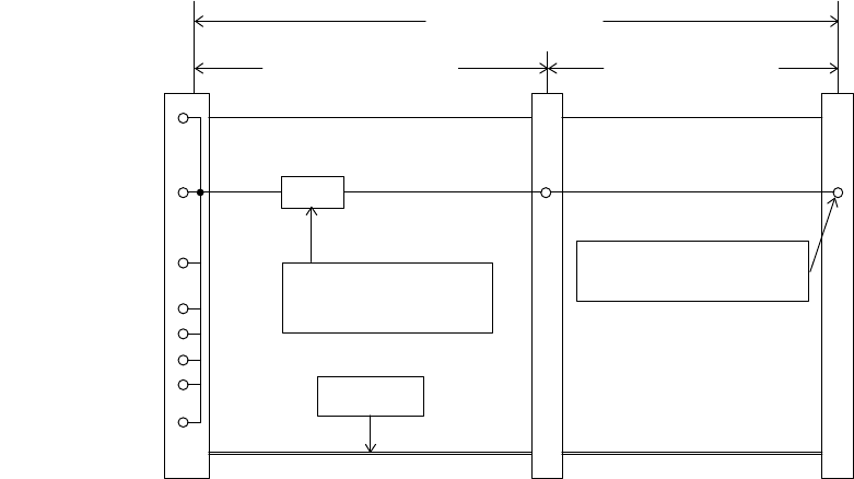
Connector 2
Connector 1
System Board
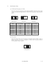
Connector
Pin 2 (Ground)
Pin 19 (Ground)
Pin 22 (Ground)
Pin 24 (Ground)
Pin 26 (Ground)
Position 1
Pin 34 contact
(PDIAG-:CBLID- signal)
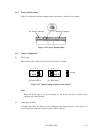
254.0 to 457.2 mm
(10 to 18 inch)
101.6 to 152.4 mm
(4 to 6 inch)
127.0 to 304.8 mm
(5 to 12 inch)
Symbolizes Pin 34
Conductor being cut
Pin 30 (Ground)
Pin 34
Pin 40 (Ground)
Figure 3.10 Cable configuration
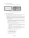
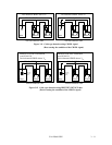
b) Host system that do not support Ultra DMA modes greater than mode 2 shall not connect
to the PDIAG-:CBLID- signal.
c) Host system that do support Ultra DMA modes greater than mode 2 shall either connect
directly to the device without using a cable assembly, or determine the cable assembly
type. Determining the cable assembly type may be done either by the host sensing the
condition of the PDIAG-:CBLID- signal (see Figure 3.11), or by relying on information
from the device (see Figure 3.12). Hosts that rely on information from the device shall
have a 0.047 µF capacitor connected from the PDIAG-:CBLID- signal to ground. The
tolerance on this capacitor shall be 20% or less.