


C141-E069-02EN4 - 14
4.6.4 Time base generator circuit
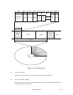
The drive uses constant density recording to increase total capacity. This is different from the
conventional method of recording data with a fixed data transfer rate at all data area. In the
constant density recording method, data area is divided into zones by radius and the data
transfer rate is set so that the recording density of the inner cylinder of each zone is nearly
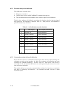
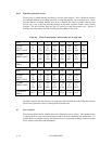
constant. The drive divides data area into 15 zones to set the data transfer rate. Table 4.2
describes the data transfer rate and recording density (BPI) of each zone.
Table 4.2 Write clock frequency and transfer rate of each zone
Zone 0 1 2 3 4 5 6 7
Cylinder
(except
MPD3130AT)
0
to
1174
1175
to
1760
1761
to
2047
2048
to
3600
3601
to
4208
4209
to
4830
4831
to
5448
5449
to
6630
Cylinder
(MPD3130AT)
0
to
1302
1303
to
1865
1866
to
2148
2149
to
3698
3699
to
4295
4296
to
4918
4919
to
5538
5539
to
6718
Transfer rate
[MB/s]
26.11 25.66 25.43 24.16 23.64 23.09 22.53 21.44
Zone 8 9 10 11 12 13 14
Cylinder
(except
MPD3130AT)
6631
to
7585
7586
to
8485
8486
to
9952
9953
to
10960
10961
to
11464
11465
to
12464
12465
to
13032
Cylinder
(MPD3130AT)
6719
to
7670
7671
to
8565
8566
to
10022
10023
to
11015
11016
to
11494
11495
to
12514
12515
to
13032
Transfer rate
[MB/s]
20.52 19.63 18.12 17.06 16.54 15.40 14.52
The MPU transfers the data transfer rate setup data (SDATA/SCLK) to the RDC that includes
the time base generator circuit to change the data transfer rate.
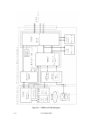
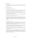
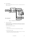
4.7 Servo Control
The actuator motor and the spindle motor are submitted to servo control. The actuator motor
is controlled for moving and positioning the head to the track containing the desired data. To
turn the disk at a constant velocity, the actuator motor is controlled according to the servo data
that is written on the data side beforehand.