


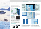

PRESENTATIONS of ECDIS
Route planning
The operators can plan and
determine the precise route with
ease, while studying the chart
data on the screen. A route can
be altered in minute detail, and
the changed route can be saved
for later use.
Radar overlay
Radar echo image overlay is optionally available in
the FEA-2107/2807. This function gives the exact match in
scale and presentation of the chart and radar echo image.
This greatly helps the operator’s observation and enhances
their accuracy.
Day/night presentation
Conning display
Typically, information on the conning display is received
from the following sensors:
Data display
When the cursor is placed upon any mark on the electronic
chart, related information about the object such as a buoy,
lighthouse, sunken vessel, etc., will be shown in the data
cell. Additionally, other navigational information including
both own ship’s navigational as well as other ship’s
information from ARPA can also be presented.
This function informs the operator beforehand of shallow
coastal water and other sea conditions that could
contribute to the ship going aground.
The information about the sea areas is acquired from
the electronic chart and ship’s draft data is preset in own
ship’s information so that possible strand can be avoided.
Antigrounding
AIS symbol
Heading
Own ship’s information
• Ship’s position
• Heading
• Course over ground (COG)
• Speed over ground (SOG)
UTC
(coordinated universal time)
Cursor information,
Distance and bearing
between own ship
and cursor
Planned route
WTP
(Waypoint)
Buoy
Cursor
Own ship’s marker
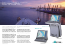
Navigate safely and efficiently with
the ECDIS route planning and monitoring
AIS information
• Name
• IMO MMSI number
• Position
• Speed
• Course
• CPA
• TCPA
• Range
sPosition sensors
sWind sensor
sGyro
sRate of turn gyro
sLog/Dual-axis log
sEcho sounder
sRudder
sPropellers
sThrusters
A variety of navigation
information, which is input
from up to sixteen onboard
sensors, can be graphically
displayed on thee screen.
Up to eight sensors provide
the analog data, and the other
eight provide the serial data.
The information is displayed in six predefined place
where the operators can arrange the layout.
Status bar
• Presentation mode
• Vector mode and vector time
• Planned route, chart name
• Name of pilot data
• Source of target data
• Predictor time
Radar overlay dialog box
Operators can have controls for
adjustment of the radar image - gain, sea
clutter, rain clutter, echo trail, interference
rejector, echo stretch and noise rejector.