


Magnum 6K25 Managed Fiber Switch Installation and User Guide (04/06)
22
www GarrettCom com
..
3.2 Connecting Ethernet Media
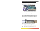
The Magnum 6K25 Switches are specifically designed to support all
standard Ethernet media types within a single Switch unit. This is
accomplished by using a family of different port Modules which can be
individually selected and configured per-port. See Section 2.4 for a description
of the PMs.
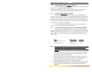
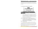
The various media types supported along with the corresponding IEEE
802.3 and 802.3u standards and connector types are as follows:
IEEE Standard
Media Type Max. Distance Port Module
Fiber:
100BASE-FX
m
m
1
Fiber 220m ( ft) GBIC-SXSC
sgl.m
2
Fiber 5Km GBIC-LXSC
100BASE-FX
m
m
1
Fiber 2.0km (6,562 ft) 6K6-MSC, -MST
sgl.m
2
Fiber 18.0km (95K ft) SSC, SSCL
small form factor
m
m
1
Fiber 2.0km (6,562 ft) 6K8-MTRJ, -MLC
small form factor
sgl.
m
1
Fiber 15 km 6KP8- SLC
Copper:
10BASE-T and 100BASE-TX twisted pair 100m (328 ft) 6K8-RJ45
1
mm = multi-mode
2
sgl.m = single-mode
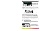
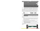
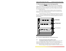
3.2.1 Connecting Fiber Optic ST-type, “twist-lock”
The following procedure applies to installations using a PM with ST-type fiber
connectors. This procedure applies to ports using a 6K25 module, MST-type port.
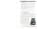
1. Before connecting the fiber optic cable, remove the protective dust caps from the
tips of the connectors on the PM. Save these dust caps for future use.
2. Wipe clean the ends of the dual connectors with a soft cloth or lint-free lens tissue
dampened in alcohol. Make certain the connectors are clean before connecting.
Note: One strand of the duplex fiber optic cable is coded using color
bands at regular intervals; you must use the color-coded strand on the
associated ports at each end of the fiber optic segment.
3. Connect the Transmit (TX) port (light colored post) on the Magnum PM to the
Receive (RX) port of the remote device. Begin with the color-coded strand of
the cable for this first TX-to-RX connection.
4. Connect the Receive (RX) port (dark colored post on the PM) to the Transmit
(TX) port of the remote device. Use the non-color coded fiber strand for this.
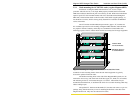
5.
The LINK LED on the front of the PM will illuminate when a proper
connection has been established at both ends (and when power is ON in
the unit). If LINK is not lit after cable connection, the normal cause is
improper cable polarity. Swap the fiber cables at the PM connector to
remedy this situation.