


Magnum 6K25 Managed Fiber Switch Installation and User Guide (04/06)
32
www GarrettCom com
..
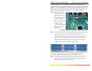
NOTE: All 6KPM slots need not be filled in order for the Magnum 6k25 unit to be
operational. When leaving 6KPM slots empty, always use a face plate (Magnum 6K8-
BLNK) to cover the slot opening in the front panel. This will maintain proper cooling
air flow, safety, and operation as required by FCC, CE, and other regulations.
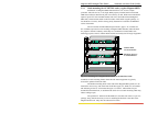
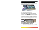
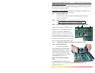
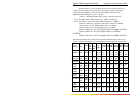
Step 6. Now screw down the
daughter board with 6
#440 screws, so that it
holds the daughter board
securely. The figure
below shows the top view
of 6KPM card after
successfully installing the
6KPM cards inside the
Magnum 6K25.
Fig. 3.5.2g Top View : 6KPM Module installed inside a 6K25
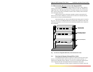
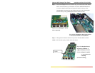
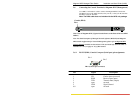
Step 7. Once the installation of granddaughter and daughter modules is done, the front
panel screen plates need to be placed on the front of the chassis cover to
complete the installation process for that port module. The front panel screen
plate comes along with the package of port module separately along with
brackets and 6 #256 flat head screws. The brackets and screws have been
installed inside of the top cover as shown in Fig. 3.5.2h.
Fig. 3.5.2h Inside view of chassis cover (from the rear), showing the front panel
screen plates installed inside the chassis cover using brackets and screws
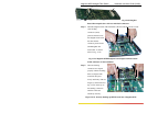
Step 8. Once all 6KPM cards have been installed (including faceplates for empty
slots), the chassis cover should be replaced. Make sure the chassis cover is
aligned properly before securing the enclosure.