Magnum P62-Series Hardened Switches Installation and User Guide (08/03)
26
www GarrettCom com
..
Operating Shock and Vibration: meets Bellcore GR-63-CORE Sections 4.4.1 and 4.4.3
NOTE : For best results at high-temperature, fasten the metal case of the PSX-A unit to be in
contact with a vertical surface (such as pedestal) that has good heat conducting properties.
Remove rubber “feet”, if present, to enhance metal-to-metal contact and provide the best heat
transfer away from the PSX-A unit.
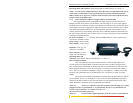
3.3.3 Power the P62-5V w/DC Pwr Supply (PSX-T) at 125/250 VDC
The rugged Magnum P62-5V Hardened Switch also supports 125V/250 VDC power
through a separate Power Source unit, the PSX-T. The wide range of AC power input qualifies
this product for use worldwide, in almost any temperature environment. The 125/250 VDC power
source (PSX-T) provides a rugged power supply enclosed in a metal case that also acts as a heat
sink, enabling extended temperatures to be accommodated. The PSX-T also includes reverse-
polarity protection to prevent damage in case the unit is accidentally hooked up backwards. The
DC power output cord comes with a military-style screw-lock female plug for secure attachment
to the P62-5V Hardened Switch.
DC Power Terminals: “+”, “-”, internally floating GND terminal for “earth” or ground wire
connection to the PSX-T chassis
Input Voltage: 100 to 275VDC
Power Output : 5VDC, 3Amps
Input Fuse: 3AG type, 0.5
Amp; spare is included
Power Capacity: 15 watts
output, 70% min efficiency
Operating Shock and
Vibration: meets Bellcore GR-63-CORE Sections 4.4.1 and 4.4.3
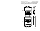
PSX-T INSTALLATION
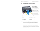
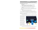
This section describes the proper connection of the -125V/250 VDC leads to the –
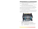
125/250 VDC power terminal block on the PSX-T Power Source (as shown in Figure above)
The –125/250 VDC terminal block on the External PSX-T is located on the left side of the unit
and is equipped with three (3) screw-down lead posts, covered by a removable safety shield or
cover. The power terminals are identified as positive (+) and negative (-), and they are floating
inside the unit so that either may be grounded by the user. The chassis is “earth” or ground
(GND).
The connection procedure is straightforward. Simply insert the DC leads to the PSX-T’s
power terminals, positive (+) and negative (-) screws. The use of Ground (GND) is optional; it
connects to the PSX-T chassis. Ensure that each lead is securely tightened, then replace safety
shield. When power is applied, the green PWR LED will illuminate
NOTE (1): Always use a voltmeter to measure the voltage of the incoming power supply
and figure out the +ve potential lead or -ve potential lead. The more +ve potential lead will
connect to the post labeled “+ve” and the rest to the “-ve”.
The GND can be hooked up at the last.
NOTE (2): For best results at high-temperature, fasten the metal case of the PSX unit


