


Magnum Quad-Series Fiber Switches Installation and User Guide (06/03)
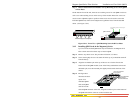
Step 2.
with top and bottom part and
ssembled together with the help of 20 Philips head screws. There are 7 screws located
n front-top of the unit and three screws each on the left and right edges. Remove these
screws. Once these are removed, the top cover is easily lifted off the chassis base. When
oved, the interior of the unit is exposed.
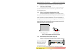
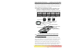
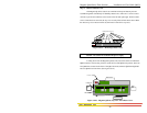
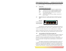
Figure 3.9.1a: Removing Chassis Cover
Caution: Be careful not to disturb the power supply.
Remove Chassis Cover
The Magnum Q-Series chassis are combined
a
o
the chassis top cover has been rem
20 Phillips Head Screws on Top
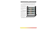
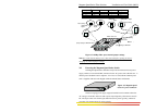
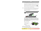
Looking that there are individual
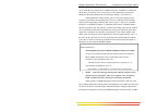
PM connector sockets along with two stand-offs for each QPM card position. There are
our QPM slots located on the front of the QS5116 model, whereas QS580 and QS5108
has two
Figure 3.9.1b: Magnum QS5116, Top View with Chassis Cover
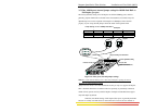
Power Input
PWR
GARRETT
down into the Magnum Q-Series unit, notice
Q
f
QPM slots in the front. (See Figure 3.9.1b).
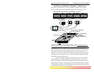
TopChassis Cover
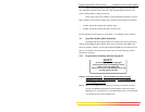
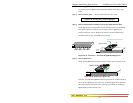
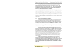
Magnum QS5116
Fiber Switch
Front of Unit
Media Connector
with electronic
elements
Left
Side
Cooling Fan
Power Supply Board
Right
Side
LED Status Slot
Eight QPM Slots
AC Power Input
Back of Unit
26
www GarrettCom com
..