


GD Systems
Page - 6 Windmill
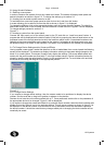
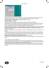
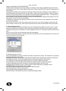
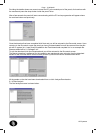
Location text The location text cannot be changed on this screen and is displayed for reference only.
Zone number The zone number cannot be changed on this screen and is displayed fore reference only.
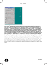
Initial Delay: Setting the initial delay will cause the system to display an alarm condition immediately and
then delay for however many seconds set before operating any sounders or outputs. If any outputs or
sounders are required to operate immediately in the event of an alarm condition, this value should be set to
zero. The second delay can then be used to change the alarm operation after the delay period. Sounder
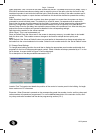
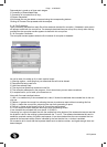
Circuits Each main control panel is fitted with 2 sounder circuits (Cct 1 & 2). By use of an expansion card
(EDA-510) this can be increased to 4 (Cct 3 & 4). In an alarm condition they can be programmed to switch
24V (On), pulse on for 1 second and off for 1 second (Int1), pulse on for 1 second and off for 2 seconds
(Int2) or not to operate (Off). The appropriate option box should be selected for the appropriate sounder
circuit. The booster panels can only have 2 sounder circuits (Cct 1 & 2) which if required can be modified (
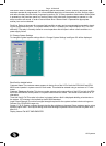
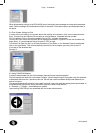
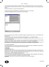
a small hardware modification) to become auxiliary circuits (Aux 1 & 2) Aux. Relay Each main control panel
is fitted with two auxiliary relays with the capability of being expanded to four with an EDA- 510 interface
card. In an alarm condition for a device the relays can be individually programmed to operate (On) or not
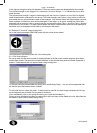
operate (Off). Care should be taken as by default the aux 2 relay is for common fault and is fail safe. If this
is being used to signal an alarm condition the fault setting in the panel options must be amended. When
wiring this relay always bare in mind the fail-safe operation. The relay is normally closed in normal opera-
tion and will open in either a fire condition or fault condition (depending on programming) or a power supply
failure.