


P
in
1 8
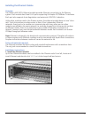
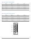
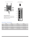
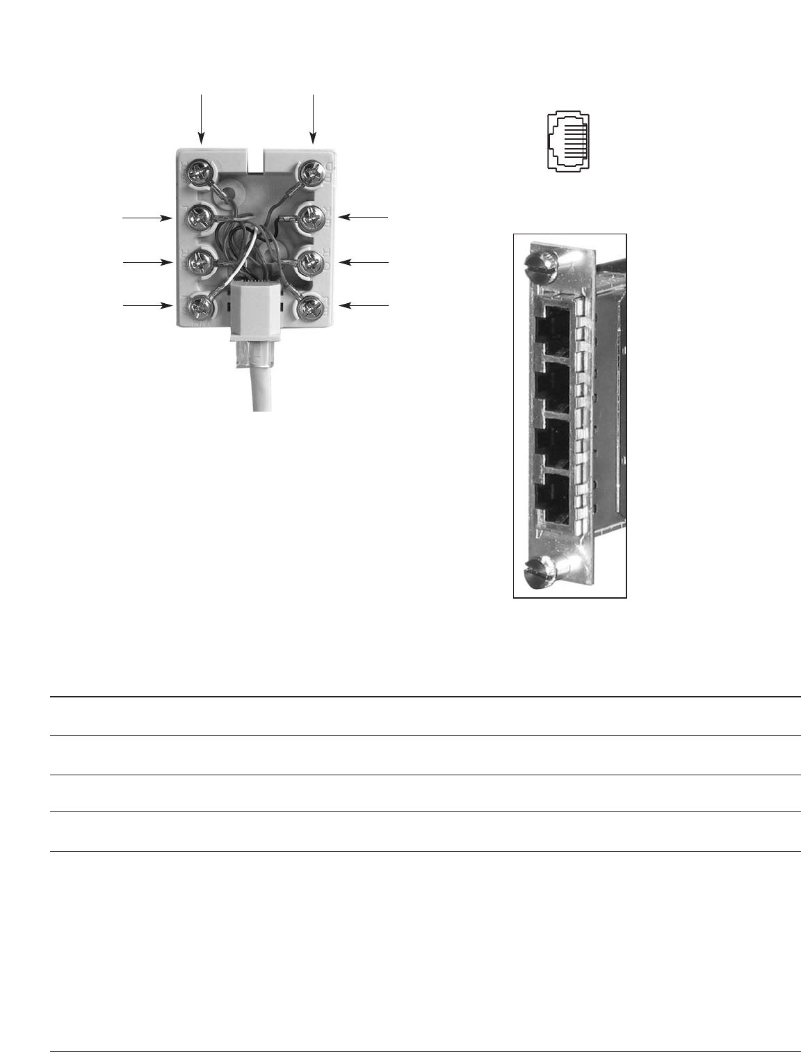
Figure 1. Terminal Block Pin Assignments
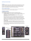
Figure 2. RJ45 Socket
(
Viewed from the rear of the unit)
8
7
6
5
4
3
2
1
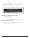
Using the breakout box
A breakout box with a 3’ CAT 5 patch cord
(supplied) can be used to interface to the
Phoenix system. Pinouts are shown in the
tables and figures above.
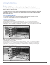
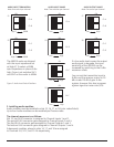
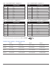
Audio module - channel sequence
RJ45-A Ch 1-2 IN
RJ45-B Ch 3-4 IN
RJ45-C Ch 1-2 OUT
RJ45-D Ch 3-4 OUT
Ch 13-14 IN
Ch 15-16 IN
Ch 13-14 OUT
Ch 15-16 OUT
Ch 9-10 IN
Ch 11-12 IN
Ch 9-10 OUT
Ch 11-12 OUT
Ch 5-6 IN
Ch 7-8 IN
Ch 5-6 OUT
Ch 7-8 OUT
Slot 15
Slot 16
Slot 17
Slot 18
RJ45-A
RJ45-B
RJ45-C
RJ45-D
19