


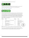
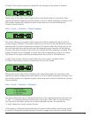
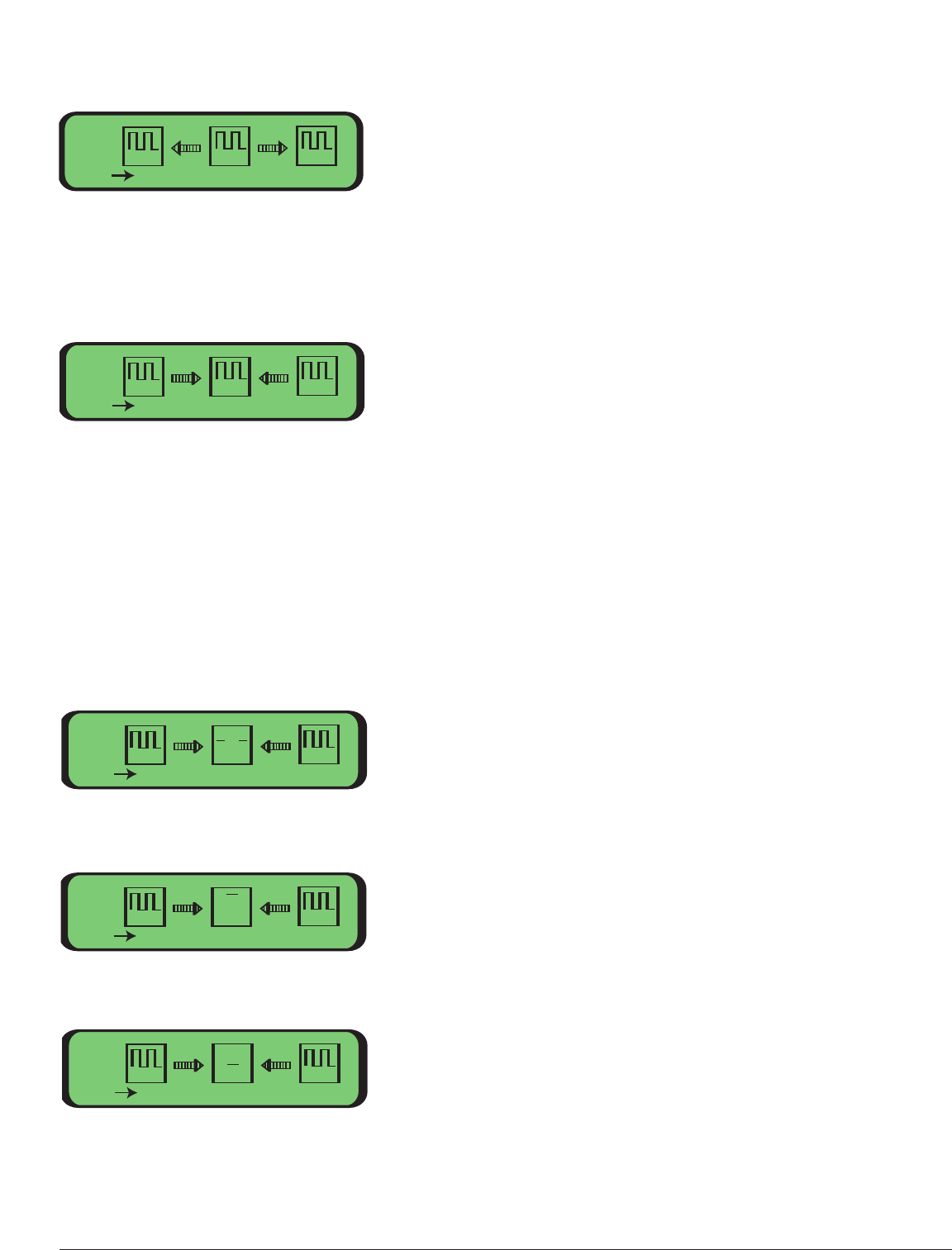
• Square Wave: Active data is detected at the data input.
Please refer to the Video Input Mapping Menu described earlier in this manual for impor-
tant notes regarding channel mapping and instructions on how to enable mappings.
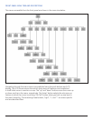
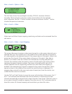
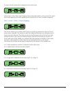
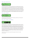
Main -> Local -> Data -> Output Mapping:
This screen allows you to select which optic port is being reviewed for each of the 16
data output channels. The number under the middle oscilloscope icon indicates which
data channel is selected. The letters under the oscilloscope icons to the left and right
indicate at which optic port the selected output channel will be looking. Arrows to t
he left and right of the middle icon indicate that the mapping is enabled. If the output
channel is not mapped to a fiber then the corresponding arrow is not shown.
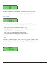
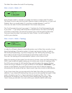
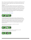
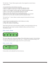
The status of the output data signal is depicted on the screen of the middle icon:
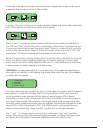
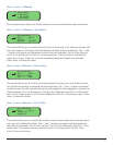
• Z: A high-impedance condition is detected at the data input
(i.e. no equipment is driving an active signal).
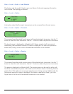
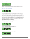
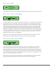
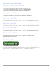
• H: A high level is detected at the data input (i.e. a logic-1).
• L: A low level is detected at the data input (i.e. a logic-0).
Data:
1
010
Exit
1
010
1
010
A B
1
1
1
Data:
1010
Exit
1010
1010
A B
B
1
A
Data:
1010
Exit
1010
1010
Z
A B
1
1
1
Data:
1010
Exit
1010
1010
H
A B
1
1
1
Data:
1010
Exit
1010
1010
L
A B
1
1
1
35