


3-2 Intelligence Panel PC User’s Manual – August 2003 GFK-2023C
3
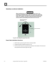
Installation Procedures
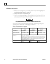
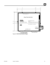
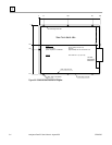
1. Make a cut-out (corresponding to size of the particular unit) in the switchgear panels
or cabinet doors (see Figures 3-1 through 3-3).
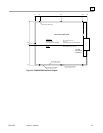
2. Insert the unit into this cut-out from the front.
3. Insert the mounting screws together with mounting blocks in the slots provided in the
metal cover and tighten all screws evenly until the surround panel covers the cut-out
securely. Maximum torque is 0.25 N-m (2.2 lb
f
-in).
Caution
Over tightening the screws will cause irreparable damage to the
front panel and break the touch screen itself.
Connect the provided power cord to the AC power supply. If additional grounding to a
grounding screw is desired, use 14 AWG gauge wire minimum.
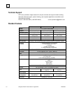
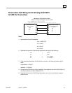
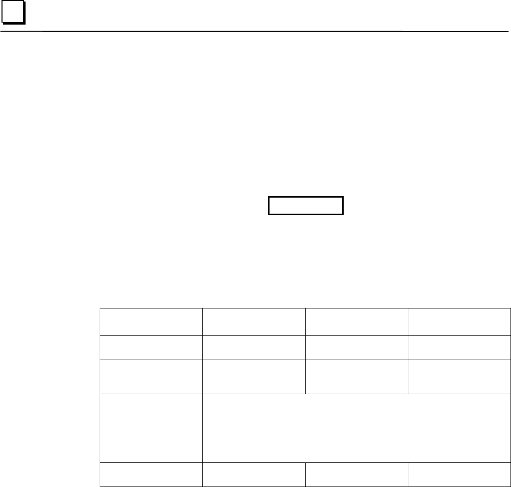
Table 3-1. Critical Dimensions for Installation
Dimension IC5002
BC5002
IC5005
BC5005
IC5008
BC5008
Cover (W x H) 313 x 252mm
23.3 x 9.9 in.
373.6 x 295.6 mm
14.7 x 11.6 in.
426 x 355mm
16.8 x 14.0 in.
Cutout (recess) (W x
H)
318 x 256mm +1.0mm
12.5 x 10.1 in. + 0.04
in.
376 x 299mm +1.0mm
14.8 x 11.8 in. + 0.04
in.
428 x 358mm +1.0mm
16.9 x 14.0 in. + 0.04
in.
Space required for
ventilation
Minimum 50mm (2 in) clearance at top and bottom of the unit. Minimum
30mm (1.2 in.) at sides.
Note additional side space consideration is required for models with CD-
ROM, depending on cabinet design. Viewed from the front, there must be
sufficient space (132 mm or 5.20 in. minimum) to the left of the units to
allow the CD-ROM drive drawer to open.
Mounting depth 177mm
6.97 in.
150mm
5.9 in.
154mm
6.1 in.