5
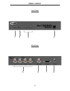
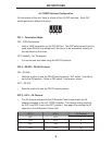
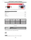
1 IR (Infrared) Receiver
This receiver will accept command for switching between input devices using
the included RMT-4IR remote control. Line of sight must be preserved between
the remote and unit for proper operation.
2 Power LED Indicator
This LED will become active once the included 5V DC power supply is properly
connected between the unit and an open wall power socket.
3 Selected Input LED Indicator
There is a 4 LED array to indicate which source is currently selected on the 4x1
3GSDI Switcher. The currently selected input will be indicated by an active LED.
4 3G-SDI Input Source Selector Button
Pressing this button will manually switch between as many as four SDI sources
connected on the rear of the Switcher. The inputs ports (item 5 below) can
accept (up to four) 3G-SDI, HD-SDI or SDI capable devices. The selected
input source is sent to the single output. Selection of input sources may also
be accomplished using the included RMT-4IR remote control or via the RS-232
serial communication port.
5 3G-SDI Inputs 1-4
These inputs ports can accept BNC connections from (up to four) 3G-SDI, HD-
SDI or SDI capable devices.
6 3G-SDI Output
This output will accept a single 3G-SDI, HD-SDI or SDI output device with a
standard BNC connector.
7 RS-232 Serial Communications Port
This port is used to control input source swithcing on the 4x1 3GSDI Switcher.
Please see page 10 for complete details on the serial communication features
that are used on this product.
8 5V DC Power Receptacle
This receptacle will require power from the included 5V DC power supply for
proper operation. Connect the included power supply between this port and an
open wall power socket.
PANEL DESCRIPTIONS


