5
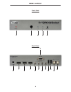
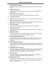
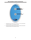
1 LED Power Status Indicator
This LED will be active once power is being supplied by the included 5V power
supply.
2 Infrared (IR) Receiver
This IR receiver will accept switching commands from the included RMT-2IR
remote control.
3 LED Input Status Indicator 1 & 2
This currently selected source input will be indicated with an active LED.
4 Input Selector Button
Pressing this button will cycle the input, 1 or 2, which will be selected for output.
5 RS-232 Communications Input
Switching commands can be initiated by using a serial communications device
and this port. For more information please see page 11.
6 5V DC Power Input
This receptacle will accept power via the included 5V DC power supply.
7 DisplayPort Input 1 & 2
This port will accept a single standard DisplayPort source device. Two ports are
available for use.
8 DisplayPort Output
This port will accept a single standard DisplayPort output device. The currently
selected DisplayPort input source will be output via this port.
9 3.5mm Analog Audio Input 1 & 2
This port will accept audio from a single 3.5mm analog mini-jack source. Two
ports are available for use and are associated with DisplayPort inputs 1 & 2,
respectively.
10 3.5mm Analog Audio Output
This port will accept a single 3.5mm analog mini-jack cable for connection to an
amplifi ed audio device. The currently selected audio input source will be output
via this port.
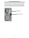
11 Infrared (IR) Receiver Extension
This port will accept an optional IR Receiver Extension product (part# EXT-RMT-
EXT-IR) for relocation of the IR receiver. This port can be used for additional
switching options. Please see page 12 for more information.
12 USB Type A Port
This port will accept a USB Type A device for use by the source device. Two
ports for the simultaneous connection of two USB devices.
13 USB Type B Port 1 & 2
This port will accept a single USB Type B cable for connection to a USB source
device. Two ports are available for use and are associated with DisplayPort
inputs 1 & 2, respectively.
PANEL DESCRIPTIONS


