


9
RMT-8IR REMOTE AND 8X1 SWITCHER CONFIGURATION
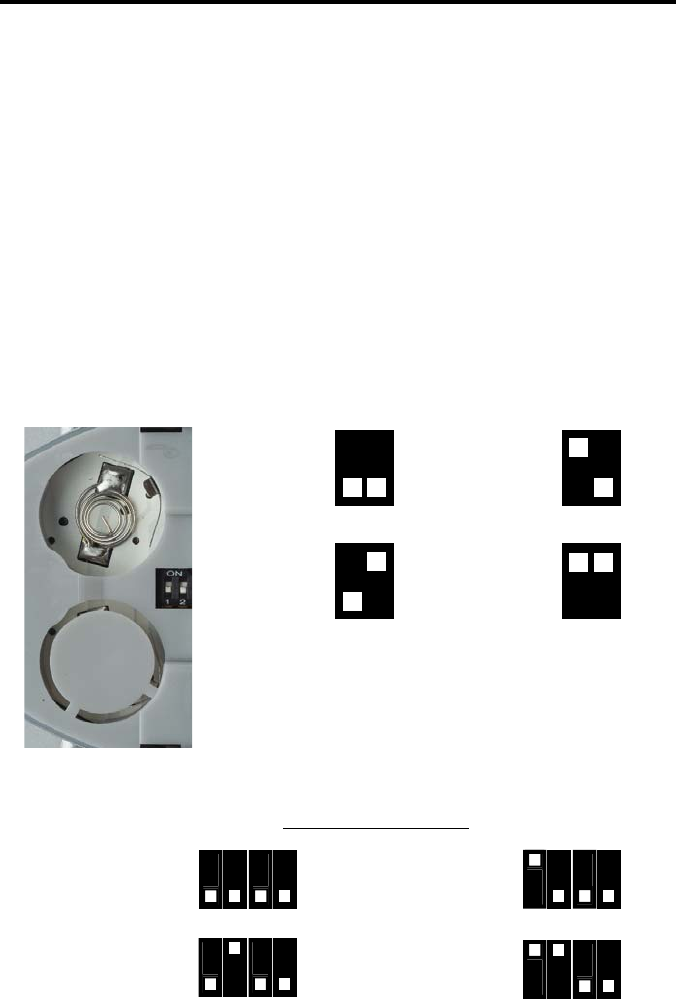
How to Resolve IR Code Confl icts
In the event that IR commands from other remote controls confl ict with the
supplied RMT-8IR remote control, changing the remote channel will alleviate this
issue. The RMT-8IR remote control and the 8x1 DVI DL/SL Switcher both have
banks of DIP (Dual Inline Package) Switches for confi guring the remote channel
that both units use to communicate. These settings must exactly match each
other for proper operation.
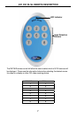
The DIP Switch bank on the RMT-8IR is located underneath the battery cover.
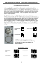
DIP Switch banks for the 8x1 DVI DL/SL Switcher are located on the underside of
the unit beneath a black piece of metallic tape. One DIP switch bank (4-switch)
is for the adjustment of remote control frequencies and switch behavior. The
other DIP switch (8-switch) is reserved for Gefen use only. DIP Switches 1 and
2 on the RMT-8IR directly correspond to DIP Switches 1 and 2 on the 8x1 DVI
DL/SL Switcher. Only switches 1 and 2 (of 4 in that bank) are used for IR Code
settings.
Remote Channel 1:
Default
1 2
Remote Channel 2:
1 2
Remote Channel 3:
1 2
Remote Channel 4:
1 2
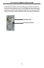
Left: Picture of the opened rear battery
compartment of the RMT8-IR remote showing
the exposed DIP Switch bank between the
battery chambers.
8x1 DVI DL/SL Switcher
Remote Channel 1:
Default
Remote Channel 4:
1
1
2
2
3
3
4
4
Remote Channel 3:
1
2
3
4
Remote Channel 2:
1
2
3
4