5
PANEL DESCRIPTIONS
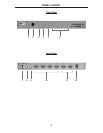
1 Power Indicator
This LED will become active once the included 5V DC power supply is properly
connected between the unit and a open wall power receptacle.
2 IR (Infrared) Receiver
This receiver will accept command for switching between input HDMI devices
using the included RMT-4IR remote control.
3 Internal EDID Mode Indicator
This LED will become active when the unit is using the pre-loaded EDID. See
page 11 for more details.
4 External EDID Mode Indicator
This LED will become active when the unit is using the EDID from the HDMI
deice connected to HDMI output port 1. See page 6 for more details.
5 Link Indicator
This LED will become active when the unit is properly connected to an HDMI
capable device on either of the HDMI output ports.
6 Input Indicators
There is one LED for each of the four input ports. The LED for the currently
selected HDMI input will be active.
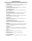
7 S/PDIF Digital Audio Output Connector
This S/PDIF output will supply supported audio formats for output to an
external audio decoder or device such as an amplifi er or receiver.
8 EDID Button
This button will toggle between the internal external EDID modes. To determine
which mode is currently being used, please note which EDID mode LED is
active on the front panel of the unit.
9 Reset Button
This button will reset the unit and force all devices in the chain to re-transmit/
re-read EDID. It is essential that the unit be reset after the EDID mode has been
changed.
10 HDMI Input Ports 1-4
Connect up to four (4) Hi-Def sources these HDMI input ports.
11 HDMI Output Ports 1-2
Connect up to two (2) HDTV displays to these HDMI output ports.
12 5V DC Power Receptacle
Connect the included 5V DC power supply between this port and an open wall
power receptacle.


