


5
PANEL DESCRIPTIONS
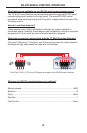
Front Panel
1 HDMI Input 1 - Attach 1st HDMI input source here.
2 Composite Video Input - Connect incoming Composite Video source here.
3 Analog Audio Input for Composite Video - Attach cable with two L+R RCA jacks to
input up to 2 channels of analog audio associated with the Composite Video input.
4 S-Video Input - Connect S-Video source here using a single S-Video cable.
5 Analog Audio Input for S-Video - Attach cable with two L+R RCA-style jacks here to
input up to 2 channels of analog audio associated with the S-Video source.
6 Component Video Input - Connect Component Video source here.
7 Analog Audio Input for Component - Attach cable with two L+R RCA-style jacks
here to input up to 2 channels of analog audio associated with the Component source.
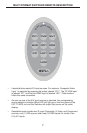
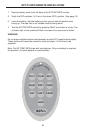
8 IR signal window - Receives IR commands from the IR Remote control.
9 Power Indicator LED - ON (red) when the Switcher is correctly powered.
10 Source Input Indicators 1-10 (blue LEDs) with Selector Buttons - Blue LEDs
Indicate the active A/V source. Buttons choose currently active Video input source.
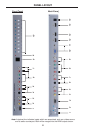
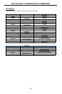
Back Panel
1 480i/576i De-Interlace Button - Converts video to a de-interlaced signal. Improves
standard defi nition sources such as gaming consoles and broadcast television.
2 Audio Delay - Adds a short delay to output audio. Useful for console gaming.
3 RS-232 Port - Attach a DB9 serial cable here to upgrade the fi rmware using an
internet-enabled computer. Please call Gefen when attempting this operation.
4 Composite Input - Attach a cable having 1 x RCA Composite Video connector here.
5 Analog Audio Input for Composite Video - Attach cable with two L+R RCA-style
jacks here to input up to 2 channels of audio associated with Composite Video source.
6 S-Video Input - Connect a single cable with an S-Video connector here.
7 Analog Audio Input for S-Video - Attach cable with two L+R RCA-style jacks here to
input up to 2 channels of analog audio associated with S-Video input source.
8 Component Video Input - Connects a Component Video input here using a cable
terminated with 3 x RCA jacks (RGB).
9 Analog Audio Input for Component Video - Two L+R RCA-style jacks allow input of
up to 2 channels of analog audio associated with the Component Video source.
10 VGA (PC) Input - Connect a std. VGA (HD15) terminated video cable from a PC here.
11 3.5mm Audio Input -- Connect a 3.5mm stereo mini-jack to input up to 2 channels of
analog audio associated with the VGA video input signal.
12, 13 HDMI Inputs 2 & 3 -- Attach 2nd and 3rd HDMI Input sources here.
14 HDMI Output -- Connect your HDMI-Compliant Display to this output on the Switcher.
15 Power Receptacle -- Connect the DC Power Supply here to activate the Switcher.