


7
RECEIVER UNIT PANEL DESCRIPTIONS
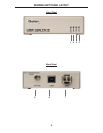
1 USB Port (1-4)
USB device input ports.
2 USB Indicator (1-4)
This LED indicates when a USB device is connected to the Device Port. Solid
green when device is plugged in and active. Off when device is in a suspend
mode or Receiver unit is powered off. Orange when the Receiver unit detects an
overcurrent condition, or if the attached USB device attempts to draw more than
the 500mA current.
3 Power Indicator
This LED turns bright blue when power is supplied.
4 Link Indicator
This LED turns bright green when a valid ExtremeUSB® link is established
between the Sender Unit and Receiver Unit.
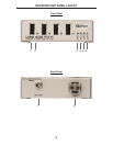
5 Host Indicator
This LED turns bright green when the USB 400 FO system is properly
enumerated on the host PC. The LED blinks when in Suspend Mode.
6 Activity Indicator
This LED turns bright amber, indicating that data transmission is active between
the Sender and Receiver. The LED blinks intermittently with or without a USB
device plugged in. When the Sender Unit and Receiver Unit are in a Suspend
Mode, the LED is off.
7 Power port
Connects to the 5V DC power supply.
8 Link Port
Connect one end of a duplex LC fi ber optic cable to this port.