


3 Generac
®
Power Systems, Inc.
2.1 INTRODUCTION TO INSTALLATION
This equipment has been wired and tested at the facto-
ry. Installing the switch includes the following proce-
dures:
• Mounting the enclosure.
• Connecting power source and load leads.
• Connecting control wiring.
• Connecting any auxiliary contact (if needed)
• Installing/connecting any options and accessories.
• Testing functions.
2.2 UNPACKING
Carefully unpack the transfer switch. Inspect closely
for any damage that might have occurred during ship-
ment. The purchaser must file with the carrier any
claims for loss or damage incurred while in transit.
Check that all packing material is completely removed
from the switch prior to installation.
Attach any lifting device to the transfer switch mounting
holes or brackets only. DO NOT LIFT THE SWITCH AT
ANY OTHER POINT.
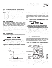
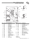
2.3 MOUNTING
Transfer switch components are generally mounted in a
standard NEMA 1 type enclosure (Figure 2.1).
Handle transfer switches carefully when
installing. Do not drop the switch. Protect the
switch against impact at all times, and against
construction grit and metal chips. Never install a
transfer switch that has been damaged.
Figure 2.1 — Mounting Dimensions for Enclosures
Install the transfer switch as close as possible to the
electrical loads that are to be connected to it. Mount the
switch vertically to a rigid supporting structure. To pre-
vent switch distortion, level all mounting points. If nec-
essary, use washers behind mounting holes to level the
unit.
2.4 CONNECTING POWER SOURCE AND
LOAD LINES
Make sure to turn OFF both the normal (Utility)
and standby (generator) power supplies before
trying to connect power source and load lines to
the transfer switch. Supply voltages are extreme-
ly high and dangerous. Contact with such high
voltage power supply lines causes extremely haz-
ardous, possibly lethal, electrical shock.
Wiring diagrams and electrical schematics are provided
in this manual. Power source and load connections are
made at a transfer mechanism, inside the switch enclo-
sure.
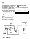
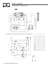
2.4.1 2-POLE MECHANISM
This switch (Figure 2.2) is used with a single phase sys-
tem, when the single phase NEUTRAL line is to be con-
nected to a Neutral Lug and is not to be switched.
Figure 2.2 — 100 Amp 2-Pole Transfer Mechanism
Solderless, screw-type terminal lugs are standard.
Conductor sizes must be adequate to handle the maxi-
mum current to which they will be subjected. The
installation must comply fully with all applicable codes,
standards and regulations.
NEUTR
AL
BRIDGE
RECTIFIER
VARISTOR
UTILITY
CLOSING COIL
LIMIT SWITCH XA1
M
ANUAL TRANSFER LEVER
LIMIT SWITCH XB1
STANDBY
CLOSING COIL
VARISTOR
BRIDGE
RECTIFIER
N1 N2
E1
E2
T1 T2
DANGER
!
Section 2 — Installation
Generac 100 Amp Transfer Switch
SWITCH
TRANSFER
GENERAC
**ALL DIMENSIONS IN:
MILLIMETERS (INCHES)
- VOIR LE SCHEMA
D'UN CIRCUIT SOUS TENSION
AVERTISSEMENT - PLUS
LIVE CIRCUIT - SEE DIAGRAM
WARNING - MORE THAN ONE
257.0mm [10.12"]
363.8mm [14.32"]
53.4mm [2.10"]
12.7mm [0.50"]
514.1mm [20.24"]
488.7mm [19.24"]