


4 Generac
®
Power Systems, Inc.
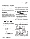
Before connecting wiring cables to terminals, remove
any surface oxides from the cable ends with a wire
brush. If ALUMINUM conductors are used, apply joint
compound to conductors. After tightening terminal
lugs, carefully wipe away any excess joint compound.
All power cables should enter the switch next to trans-
fer mechanism terminals.
Connect power source load conductors to clearly
marked transfer mechanism terminal lugs as follows
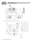
(Figure 2.3).
1. Connect NORMAL (utility) power source cables to
switch terminals N1 and N2.
2. Connect STANDBY source power cables to transfer
switch terminals E1 and E2.
3. Connect customer LOAD leads to switch terminals
T1 and T2.
Conductors must be properly supported, of approved
insulative qualities, protected by approved conduit, and
of the correct wire gauge size in accordance with appli-
cable codes.
Tighten the wire into lugs to the following torque:
• 100 Amp Switch: 50 Inch-Pounds
Make sure to maintain proper electrical 1/2 inch clear-
ance between live metal parts and grounded metal.
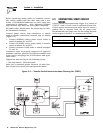
2.5 CONNECTING START CIRCUIT
WIRES
Control system interconnections (Figure 2.3) consist of
UTILITY 1 and 2. LOAD 1 and 2; and leads 23 and 194.
Control system interconnection leads must be run in a
conduit that is separate from the AC power lead.
Recommended wire gauge sizes for this wiring depends
on the length of the wire, as recommended below:
Section 2 — Installation
Generac 100 Amp Transfer Switch
Figure 2.3 — Transfer Switch Interconnections (Drawing No. C3921)
MAXIMUM WIRE LENGTH RECOMMENDED WIRE
SIZE
460 feet (140m) No. 18 AWG.
730 feet (223m) No. 16 AWG.
1,160 feet (354m) No. 14 AWG.