


2
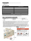
TABLE 1 - SPECIFICATIONS
Model: 6294, 6408, 6376
# Circuits Provided on Transfer Switch 6
Max # Circuits 10
REQUIRED BREAKER FOR MAIN LOAD CENTER (not included) 60 amp 2-pole
Utility Main Breaker 60 amp 2-pole
Generator Main Breaker 30 amp 2-pole
Breakers Provided with Unit 2 – 15 amp 1-pole, 2 – 20 amp 1-pole, 1 – 20 amp 2-pole
Max GEN Watts 7500 continuous / 9000 surge
Max GEN Amps 30 Amps
Voltage 125/250 Volts
NEMA Type Enclosure 1 – Indoor Only
NEMA Configuration of Male Inlet in Power Inlet Box L14-30
Phase 1
Minimum Gauge Cord Size 10/4
*Note: If Ground Fault Circuit Interrupters (GFCI), Arc Fault Circuit Interrupters (AFCI), or Surge Protector Circuit Breakers were used as the branch circuit protector in the main load center, they
MUST be used in the transfer switch. GFCI and AFCI breakers require an isolated neutral connected from the load to the GFCI or AFCI. The load neutral needs to be connected with a wire nut to a
3-6 foot piece of white wire, run through the harness conduit to the transfer switch and connected to the "load neutral" lug or pigtail on the GFCI or ACFI breaker. Because GFCI and AFCI circuit
breakers can take up more than one space, the overall maximum number of circuits may be reduced from the number shown. Not all brands of GFCI and Arc Fault breakers will fit.
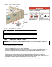
STEP 1: PLANNING YOUR INSTALLATION:
1. Determine the appliances, circuits or equipment you want to operate with generator power during a power outage, such as:
• Refrigerator/Freezer
• Furnace Blower (gas/oil only)
• TV / Radio
• Lighting
• Water Heater
• Garage Door Opener
• Microwave, Coffee Maker
• Well Pump
• Security System
• Sump Pump
• Computer, Fax and Printer, Phone
• Aquarium
2. Determine the amps required for each appliance by reading the label on the appliance. IMPORTANT: No appliance should have an amperage rating that
exceeds the GEN MAIN breaker rating in the transfer switch (See Table 1). The total amperage of all circuits can exceed the generator rating, but not all circuits
will be able to be used concurrently.
3. Assign the circuit # in the load center to a circuit (A2, B2, etc.) in the transfer switch matching the size of the circuit breaker in the load center to the circuit
breaker in the transfer switch. Once you’ve determined which circuits you want to connect and the appropriate amperage, you will be ready to begin installing
your transfer switch.
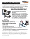
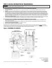
4. The location of your load center/electrical panel in your home or business will determine where the transfer switch will be installed. Refer to the illustrations
below. In addition to the transfer switch, you may need additional accessories to complete your generator transfer switch installation, such as a generator cord
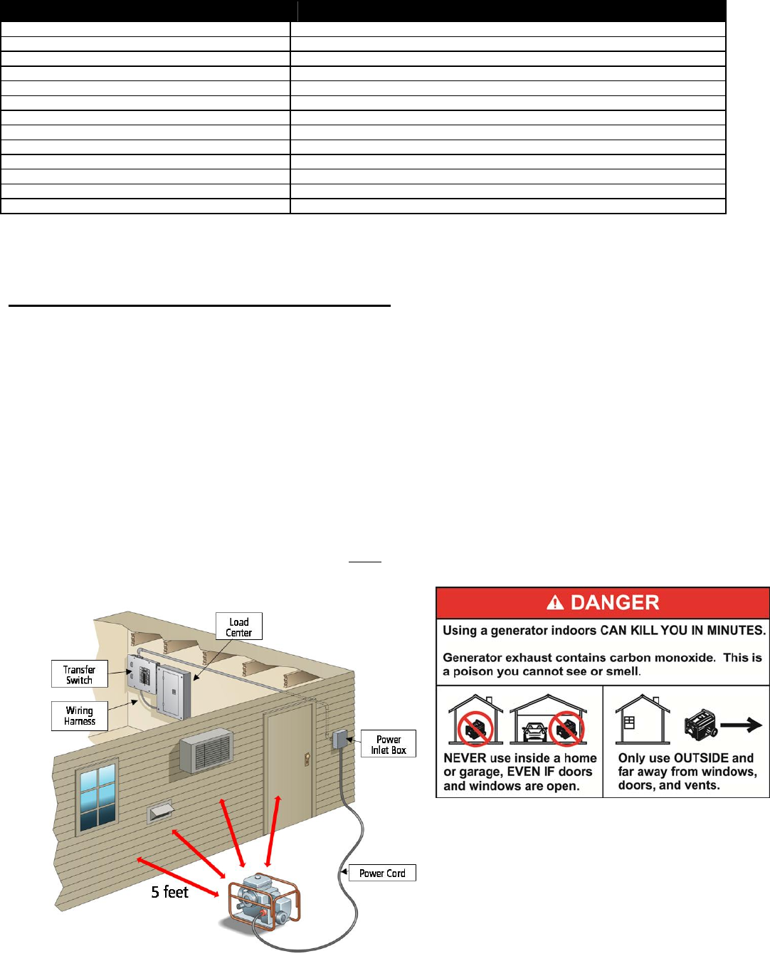
and power inlet box. Use the generator cord to connect your generator to the power inlet box outdoors. NEVER run a generator in an enclosed area! If your
load center is in a basement or interior room, you should install a power inlet box on the exterior of your house or building to avoid running the generator cord
through a door or window. Once you have all of the essential components for your specific needs, you may proceed with the installation.
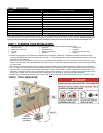
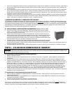
5. Determine where you will install the power inlet box on an exterior wall at least 5 feet from any openings (doors, windows, vents, etc.). See Figure 1, below.
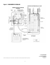
FIGURE 1: TYPICAL INSTALLATION:
Minimum
clearance from
any opening